Assembly and Operation
A: R82GB0EA.PMD
B: R82DE0EA.PMD
E: 170403 /T. Wenger
G: 020403 / TCS
Section - 5
Page - 3
?
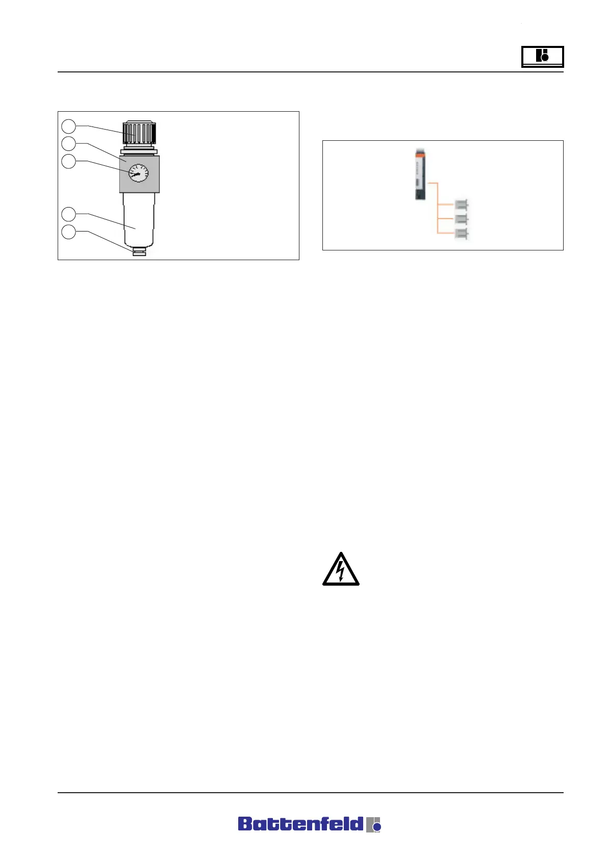
1 - Pressure control valve
adjusting knob
2 - Condensate drain
3 - Pressure gauge
4 - Condensate tank
5 - Drain plug
1
2
3
4
5
R8B2_133.PDF
R8B2_013.PDF
5.2.3 Maintenance unit
The cleaner removes any liquids and solid
materials in the compressed air flow and
regulates the air pressure.
The cleaner may only be used with properly
processed compressed air which does not
contain any aggressive agents.
A filter and a water separator remove any solid
particles and water from the compressed air.
This protects the downstream pneumatic
elements from premature wear.
Attention!
The robot system pneumatics may only be
operated using oil-free air!
5.3. Electrical systems
5.3.1 Electric motors
General:
The three linear axes on the 3-axis handling
device are driven by three motors which are
controlled by a digital servo booster. (B&R/
Type:8V1090.00-2)
Axis change-over:
The motors are activated together with the required
digital inputs/outputs. (e.g. HW limit switch)
The drive is not controlled when it is not moving.
The holding brake keeps the axis in position when
the servo booster is not activated.
The booster communicates with the CP276
controller via CAN. (refer to Section 5.4.2 PCS)
Connections are specified in Section 4.2 Transport
and Installation – Electrical connections.
Electrical components may only be serviced
by qualified electricians!