3 Disassembly / Assembly
3 - 14 Infusomat® compact
plus
P 1.0
EN
For internal use, only
Closing the unit
✓ The following modules are mounted in the housing, upper part:
■ Processor board and display board with display
■ Accessory connector
■ Loudspeaker
✓ The power supply is installed in the housing, bottom part.
✓ The housing front has been mounted to the housing, bottom
part, with the following modules installed in the housing front:
■ Pump (including stepper motor and encoder PCB)
■ SHK (including SHK board)
■ Air sensor and pressure sensors
1. Place the upper and the lower part of the unit side by side (see
Fig. 3 - 14).
2. Reconnect all plug connections.
3. Insert the fixing plate (Fig. 3 - 14 / Item 3).
4. Carefully place the upper part of the unit onto the lower part
of the unit from above.
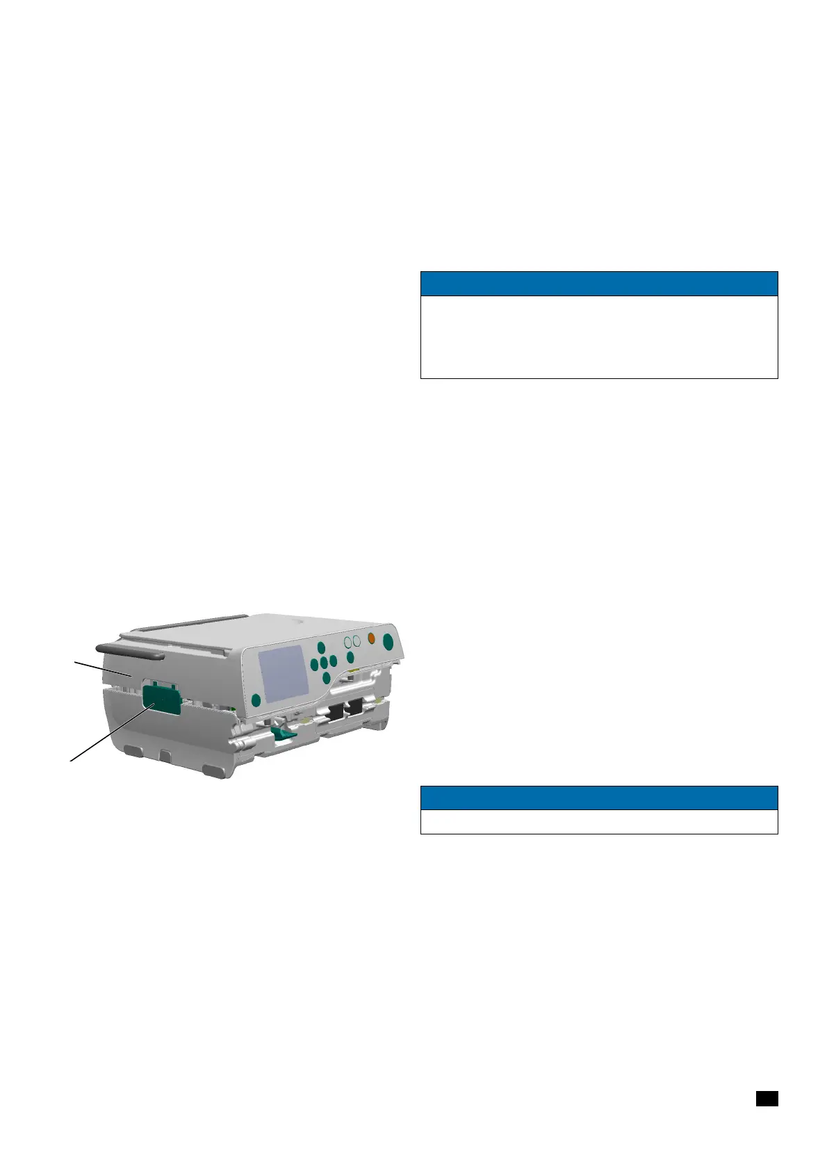
When aligning, make sure that the release button (Fig. 3 - 16 /
Item 2) is flush with the shell of the housing, upper part
(Fig. 3 - 16 / Item 1).
NOTICE
Use new screws whenever the pole clamp has been removed.
Remove residues from old precote material with a 4.3 mm / 90°
countersink. Fix the new screws with Loctite 243 if not coated
with precote
Fig. 3 - 16
1 Housing, upper part
2 Release button
NOTICE
When closing the unit, make sure no cables are trapped.