4. Theory of Operation
4-35
Wiring Interconnect Diagram
The wiring interconnect diagram shown represents major connection between modules.
See drawing 705-00022.
Theory of Operation
The FMS2000 system consists of four (4) main modules: power module, daughter board,
computer board, and AC/DC board. In addition to these main modules, there are a
membrane panel switch for user interface, roller pump, diversion valve, two (2)
temperature probe assemblies, circuit breaker, and a power entry module. The manual
is designed to familiarize the service personnel with each module so that troubleshooting
and/or replacement can be done on a module level.
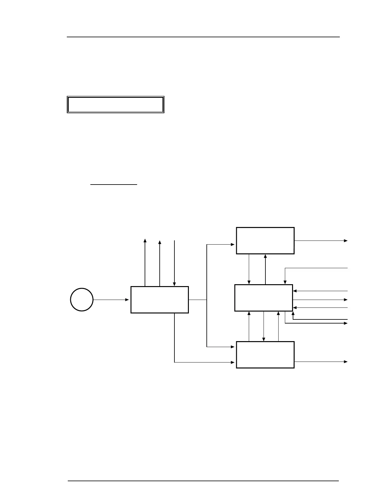
1. Power Module:
The power module consists of EMI filter board, Driver ‘A’, and Driver ‘B boards,
Heater Control board, and Heatsink Assembly.
DRIVER BOARD
'A'
HEATER
CONTROL
BOARD
DRIVER BOARD
'B'
EMI BOARD
AC
AC/DC SUPPLY CIRCUIT BREAKER
OUTPUT TO HEATER
FAULT
SIGNAL
POWER SIGNAL
CONTROL SIGNALS
FROM CPU BOARD
DC POWER
OUTPUT TO HEATER
DRIVE
CONTROL
ZERO
CROSS
SIGNAL
FAULT
CONTROL
DRIVE
HEAT ER OVER T EMP
POWER FEEDBACK
FAN CONTROL
AC
AC
ZERO CROSS
Power Module Block diagram