5. Removal and Replacement of Major Components and Modules
5-53
I. CIRCUIT BREAKER (Reference Drawing: 403-00107 (for 120V unit) or
403-00270 (for 230V unit)
Removal
1. Remove 4 X 6-32 pan head Phillips screws [(2) ¼” & (2) 1 1/8”]
connecting Circuit Breaker to Support Housing.
2. Refer to Step A Removal, 1 – 7, to remove the instrument cover.
3. Refer to Step B to remove AC/DC PCB.
4. Unplug Daughter PCB Cable.
5. Remove 4X lugs from circuit breaker.
6. Remove circuit breaker and the spacer block.
Installation
1. Install spacer block between Support Housing and Circuit Breaker.
Reinstall 4 X pan head Phillips screws connecting Circuit Breaker
to Support Housing.
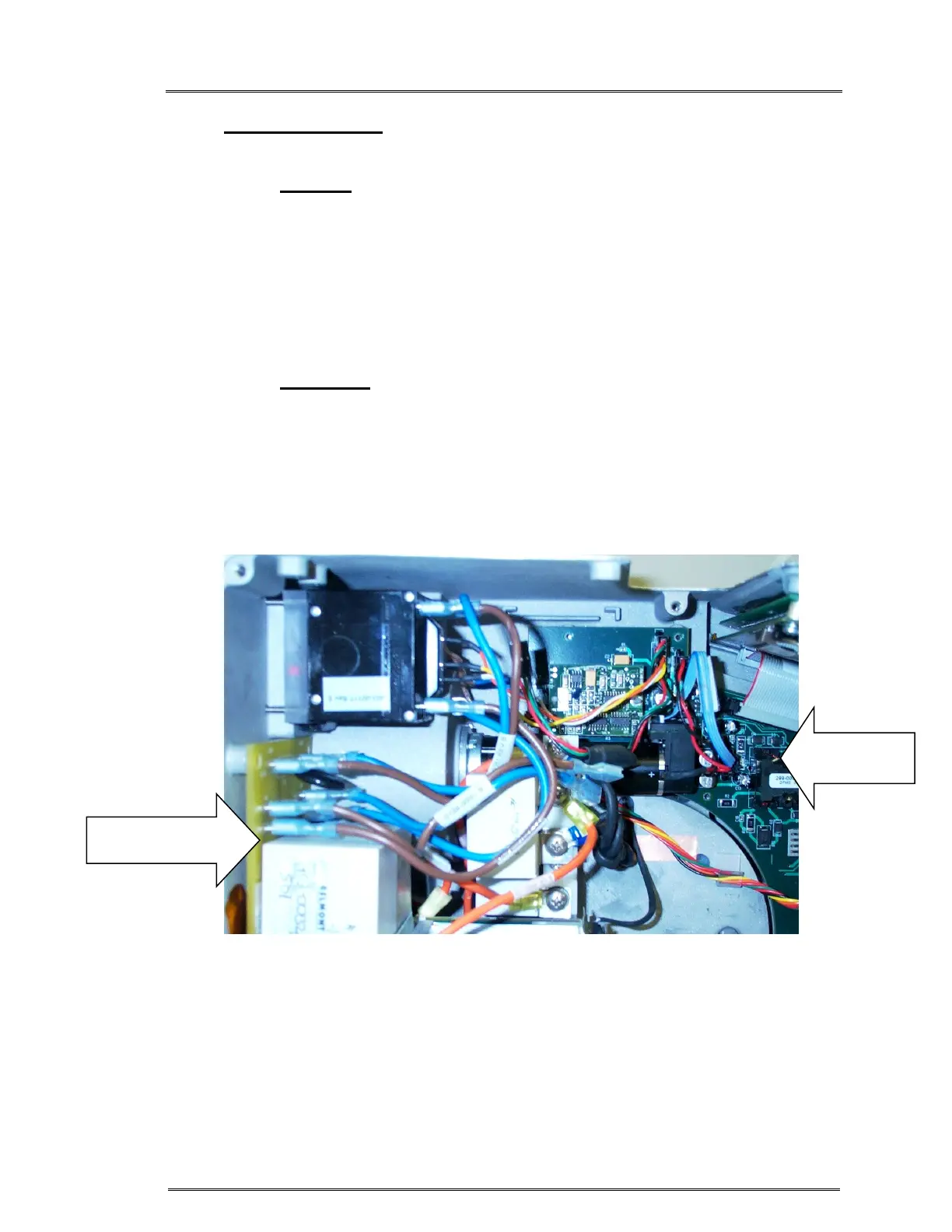
2. Reattach Daughter PCB Cable. Figure 4.
3. Reattach 4X lugs to circuit breaker. Figure 4.
4. Refer to Step B to reinstall AC/DC PCB.
5. Refer to Step A Installation, 1 – 5, to reinstall the instrument cover.
Figure 4: Attach cables and lugs as shown
Power Driver
Module
Daughter
Board