5. Removal and Replacement of Major Components and Modules
5-51
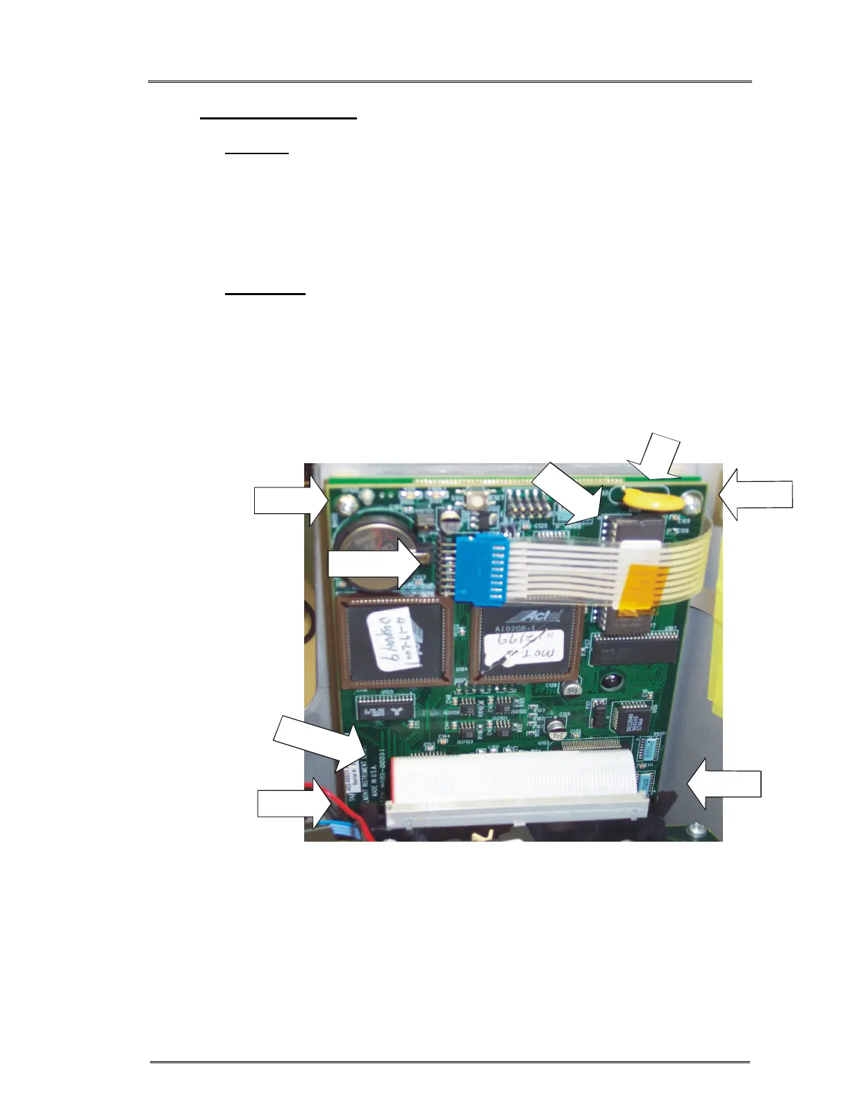
G. C152 REPLACEMENT (Reference Drawing: 403-00107)
Removal
1. Refer to Step A Removal, 1 – 7, to remove the instrument cover.
2. Ground strap must be worn.
3. Remove CPU PCB. (See Step J.)
4. Locate C152 position. Use a solder pull or solder wick to remove
left over solder.
Installation
1. Ground strap must be worn.
2. Position C152 on CPU PCB and solder in place. Figure 3.
3. Reinstall CPU PCB. (See Step J.)
4. Refer to Step A Installation, 1 – 5, to reinstall the instrument cover.
Figure 3: CPU Board
MEMBRANE
PANEL CABLE
D
A
U
G
H
T
E
R
P
C
B
C
A
B
L
E
I
C
U
1
0
P
I
N
1
FRONT
SCREW
FRONT
SCREW
BACK
SCREW