5. Removal and Replacement of Major Components and Modules
5-50
E. AIR DETECTOR SENSOR (Reference Drawing 403-00107)
(For Air detector sensor, P/N 310-00024)
Removal
1. Refer to Step K Removal, to remove the Daughter PCB,
2. Using an Exacto knife, remove the silicone from the detector.
3. Remove the two screws and the spacer from the air detector.
4. Gently push the case through the front of the Support Housing.
Installation
1. Feed the sensor connector through the front of the Support
Housing.
2. Align the detector with its mounting holes. Install the spacer (not
needed for P/N 310-00024) and fasten the two screws onto the air
detector.
3. Apply RTV silicone to entire back surface and screw holes of the
air detector.
4. Remove Air Detector Electronic PCB and discard, refer to Step D.
Refer to Step K Installation, to reinstall the Daughter PCB. Plug
the sensor connector to JP12 on the Daughter PCB.
F. BATTERY (Reference Drawing: 403-00108)
Removal
1. Refer to Step A Removal, 1 – 7, to remove the instrument cover.
2. Unplug lugs from battery terminals and slide batteries out of the
pockets in the Instrument Cover.
Installation
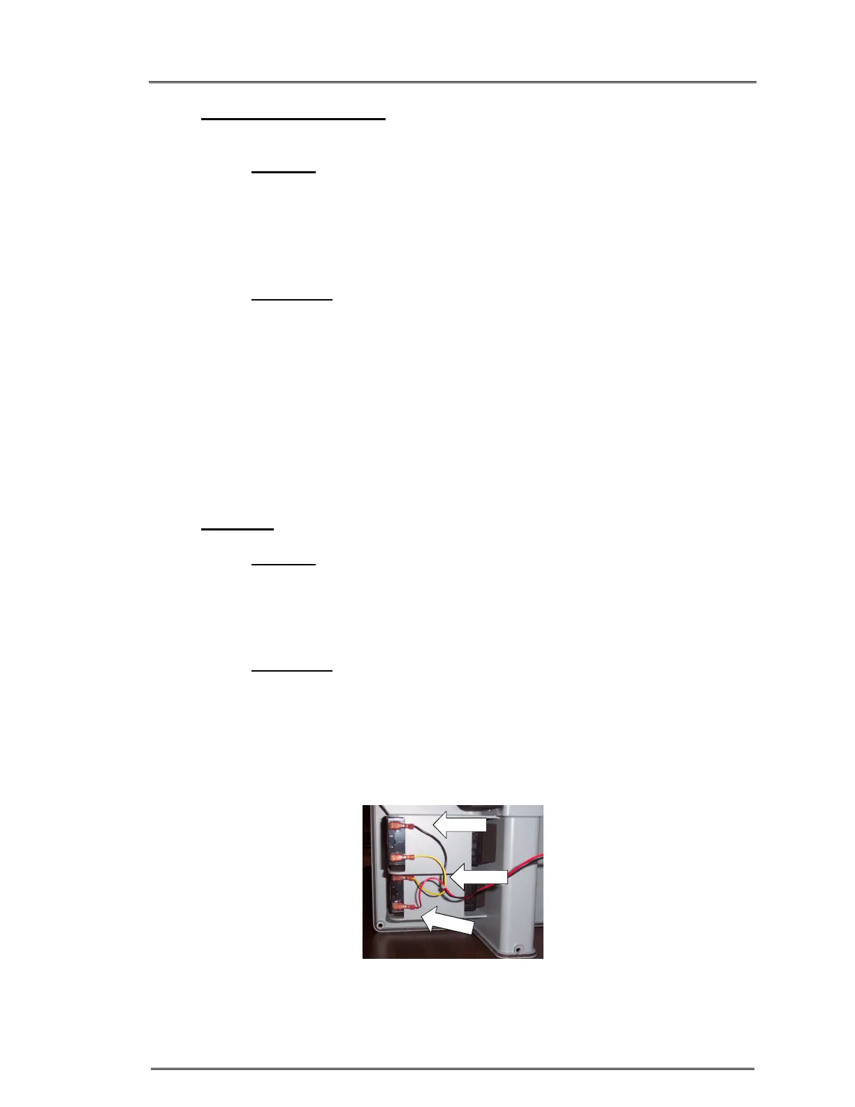
1. Reinstall ‘battery to Daughter PCB’ Cable lugs onto batteries.
(Note the proper orientation of the lugs.) Figure 2.
2. Slide batteries back into the pockets in the Instrument Cover. The
battery should be flush with the pocket edge for proper fit of the
instrument cover.
3. Refer to Step A Installation, 1 – 5, to reinstall the instrument cover.
BLK WIRE
R
E
D
W
I
R
E
Figure 2:
BLK, YEL, YEL, RED