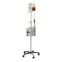
5. Removal and Replacement of Major Components and Modules
5-49
C. ACTUATOR HANDLE (Reference Drawing: 403-00108)
Removal
1. Remove 1, 8-32 x 3/4 button head hex screw, lock washer and flat
washer attaching Actuator Handle to Shaft Coupling.
2. Slide Actuator Handle off Actuator Shaft Coupling. (Do not remove
2X Disk Springs. No disk springs in older units.)
Installation
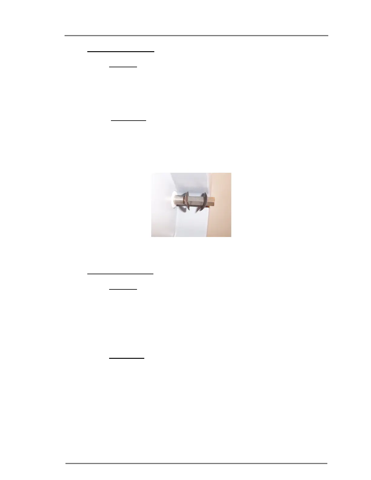
1. If the Disk Springs were removed; reinstall by orienting each disk
spring with the arcs facing each other. Figure 1.
2. Reattach Actuator Handle.
3. Reinstall 1X button head hex screw, lock washer and flat washer.
D. AIR DETECTOR PCB (Reference Drawing: 403-00107)
(If P/N 310-00024 is used, this Air detector PCB is not needed)
Removal
1. Ground strap must be worn.
2. Refer to Step A Removal, 1 – 7, to remove the instrument cover.
3. Carefully pinch the top of (2X) Air Detector Sensor Standoffs &
gently pull Air Detector PCB off.
4. If P/N 310-00024 Air Detector Sensor is used, discard this Air
detector PCB.
Installation
1. Ground strap must be worn.
2. For P/N 310-00009 Only: Place Air Detector PCB over Air
Detector Transducer Standoff, aligning pins on the back of the
PCB with the mating connectors on Daughter PCB & press down
gently until PCB snaps in place.
3. Refer to Step A Installation, 1 – 5, to reinstall the instrument cover.
Figure 1: Orient Disk Spring washers