5. Removal and Replacement of Major Components and Modules
5-62
R. IEC CONNECTOR (Power Entry Module) (Reference Drawing: 403-00107 for
120V unit) or 403-00248 (for 230V unit)
Removal
1. Unplug AC Input Cable.
2. Remove Power Driver Module. (See Step V.)
3. Remove AC Ground Cable.
4. Remove (2) lugs, from JP2 and JP5, on the EMI board
5. Remove IEC Connector by pinching the top and bottom of
connector and sliding it out of the Support Housing.
Installation
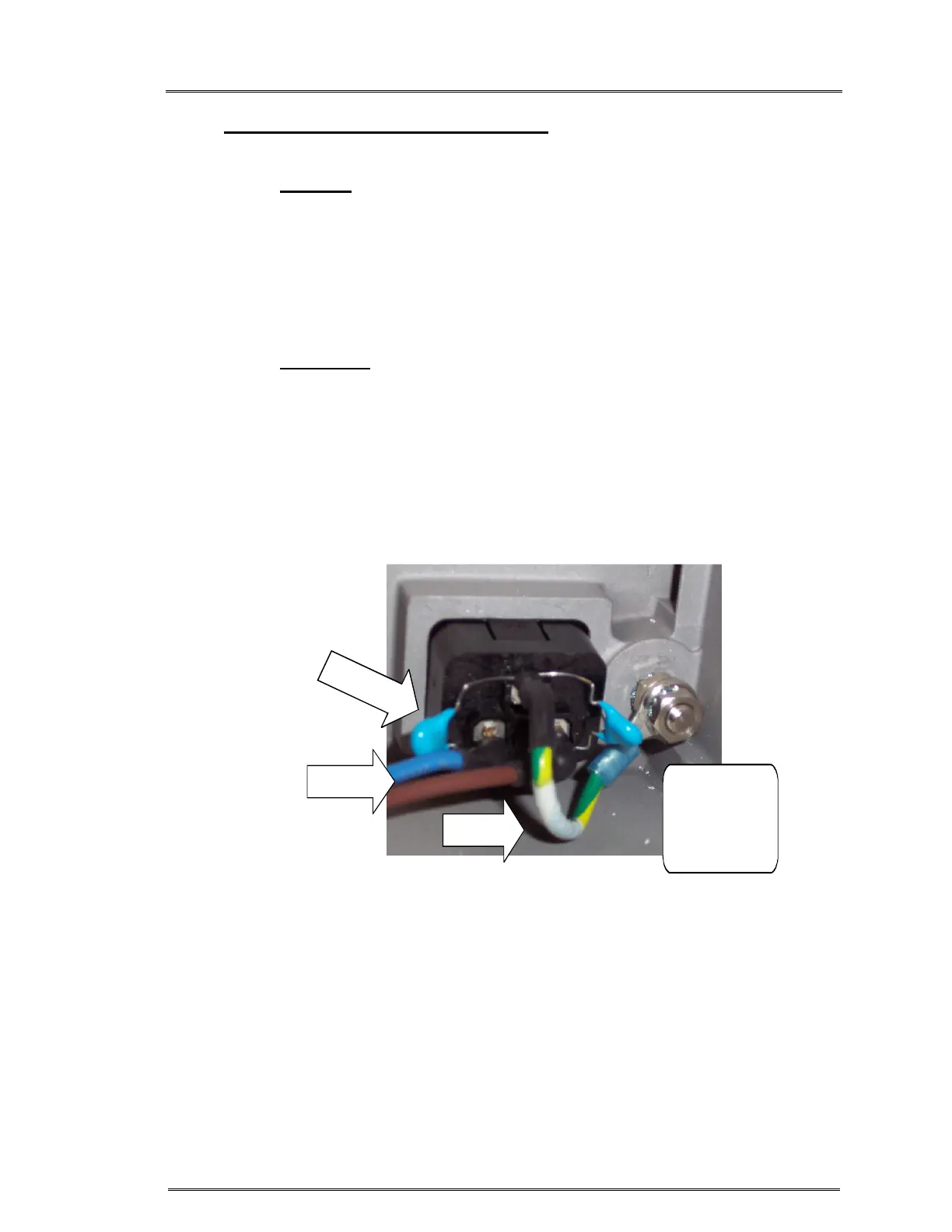
1. Attach flat washer, AC Ground Cable, flat washer, lock washer &
nut to Ground Stud in that order. Figure 7.
2. Insert IEC Connector into Support Housing and snap in place.
3. Reinstall Power Driver Module. (See Step V.)
4. Reinstall ‘Blue’ wire to JP2 and ‘Brown’ wire to JP5 on the EMI
board.
NUT
FLAT WASHER
LOCK WASHER
NUT
AC GND
CABLE
AC INPUT
CABLE
2
X
C
A
P
A
C
I
T
O
R
Figure 7