2.3 TYPE “B3” AND “B4” COUPLING BLOCKS
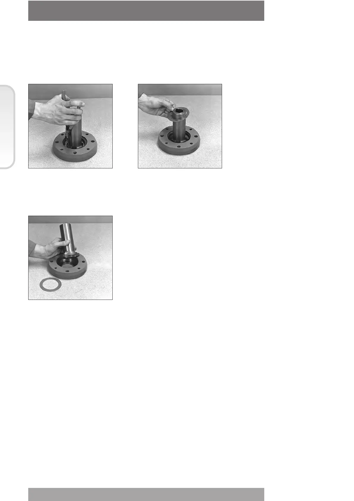
2.3.1 PREPARING THE BUSHING
Remove the fixing screws of the coupling flange.
Remove the flange and the bush.
Extract the bushing and machine
it according to the mating needs.
2.3.2 RE-ASSEMBLING THE INTERNAL PARTS
It is advisable to wash the dismantled parts with a suitable solvent; dry them with
compressed air; make sure there are no metal filings or foreign bodies; spread a film of
grease on all parts (for grease type see Sect. 618/1 Chap D).
Proceed with the assembly of the internal parts following the reverse order of the
disassembly. Fix the unit to the gear reducer as described further on.
2.4 FIXING THE COUPLING BLOCK TO THE GEAR REDUCTION UNIT
Check the integrity of the O-ring seal and place it in its slot on the coupling block. Make sure
the lugs of the drive sleeve fit in the correct slots on the bushing.
Fix the screws previously removed.
16
© Copyright by BIFFI Italia. All rights reserved.
“ICON2000”
instruction and operating manual
Section 618/1 chapt. C
Section 618/1
Remove the carbon steel
thrust ring.