SECTION 3 OPERATING THE BIS VISTA MONITORING SYSTEM
______________________________________________________________________
3-4
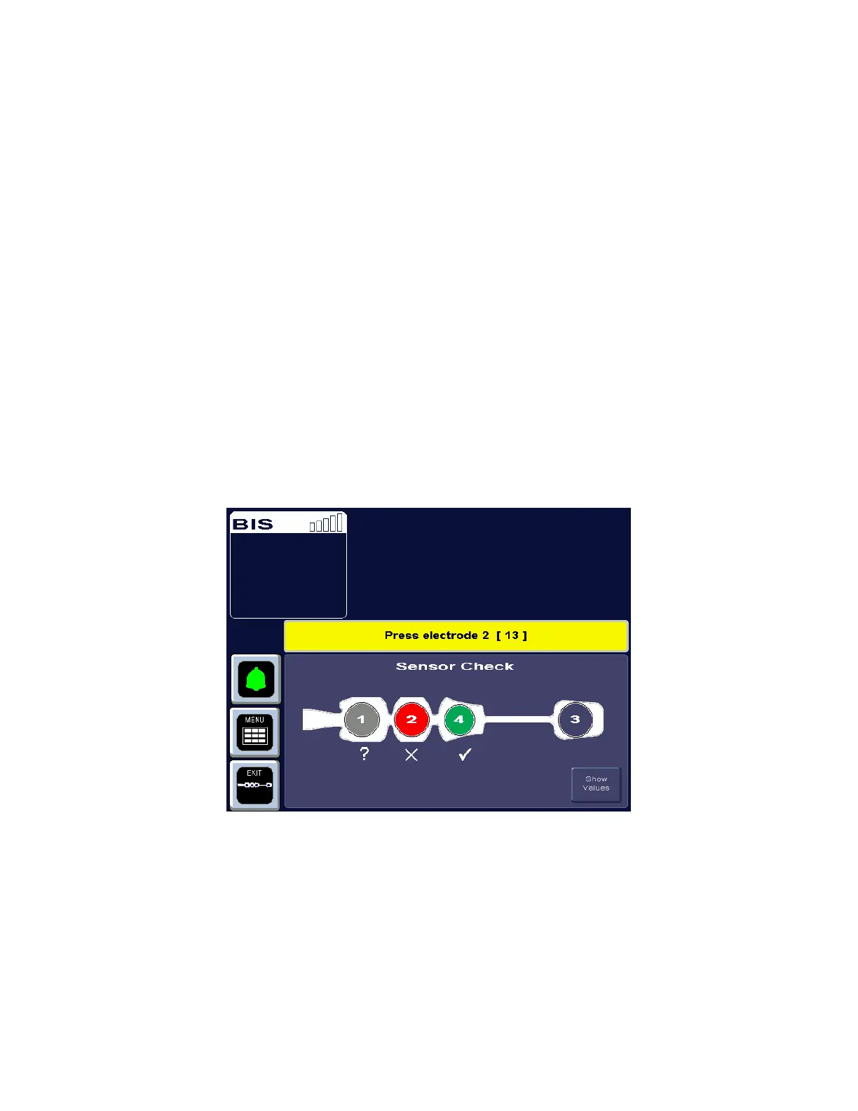
If the sensor does not immediately pass the test, or if the user has manually initiated the test,
the Sensor Check Graphic Screen displays. This screen shows the sensor with each electrode
numbered. Colors indicate the status of each electrode:
• Hollow circle – No status is available. The electrode label will appear after a few
seconds.
• Green circle with Checkmark – The electrode impedance is within the acceptable
range. When all circles are green, monitoring can begin.
• Red blinking circle with ‘X’ – The electrode impedance is not within the acceptable
range. Press the edges of the sensor to ensure adhesion and then press each circle for
5 seconds to ensure proper contact. Check all connections. If the problem persists,
remove sensor, clean skin thoroughly, and reapply sensor or apply new sensor in
accordance with instructions on the sensor packaging.
• Gray circle with Question Mark - The electrode impedance cannot be determined
due to electrical interference (noise) from another source. Monitoring will not
commence until the source of the noise has been removed and all electrodes have
passed the sensor check.
If the user has requested the Sensor Check and all electrodes pass the test, the circles return
to their original display color (blue) and the label, “PASS” displays at the bottom of the
screen.
Figure 7 - Sensor Check Graphic Screen (Values not Shown)
If user action is required, messages in the message region of the screen issue instructions.
The monitor continues updating the values until all impedance values are acceptable. The
[EXIT] touch key allows the user to exit the screen before the test has completed, however,
the Sensor Check impedance test must be successfully completed before normal processing
resumes.
For more detailed impedance information, press the [Show Values] touch key.
 Loading...