TABLE OF FIGURES
Figure 1 - Symbol Key (page 1 of 3) .............................................................................................1-6
Figure 2 - Pole Clamp...................................................................................................................... 2-4
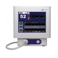
Figure 3 - The BIS VISTA Monitoring System........................................................................... 2-6
Figure 4 - Rear Panel ....................................................................................................................... 2-8
Figure 5 - BISx and PIC................................................................................................................ 2-10
Figure 6 - Connecting the PIC....................................................................................................... 3-3
Figure 7 - Sensor Check Graphic Screen (Values not Shown).................................................. 3-4
Figure 8 - Sensor Check Graphic Screen with Values Shown................................................... 3-5
Figure 9 - Screen Features – BIS Trend Data Screen................................................................. 3-6
Figure 10 - BIS Trend Data Screen with Battery Icon, Target Range, SR, and Burst Count3-9
Figure 11 - Alarm Touch Keys ....................................................................................................3-11
Figure 12 - Menu, Home, Sensor Check and Review Mode Touch Keys............................. 3-12
Figure 13 - Target Range............................................................................................................... 3-13
Figure 14 - Secondary Variable .................................................................................................... 3-15
Figure 15 - Chart Data................................................................................................................... 3-16
Figure 16 - Alarm Volume............................................................................................................ 3-17
Figure 17 - BIS/EEG Display Modes ........................................................................................ 3-18
Figure 18 - View/Save Settings.................................................................................................... 3-18
Figure 19 - Help ............................................................................................................................. 3-19
Figure 20 - Snapshot...................................................................................................................... 3-20
Figure 21 - Display SR................................................................................................................... 3-20
Figure 22 - Monitor Mode Settings ............................................................................................. 3-21
Figure 23 - Export Data................................................................................................................ 3-22
Figure 24 - Smoothing Rate.......................................................................................................... 3-24
Figure 25 - “Print” Touch Key .................................................................................................... 3-25
Figure 26 - Configuration Information....................................................................................... 3-26
Figure 27 - EEG Channels ........................................................................................................... 3-26
Figure 28 - Date and Time............................................................................................................ 3-27
Figure 29 - Language Menu.......................................................................................................... 3-28
Figure 30 - Filters........................................................................................................................... 3-28
Figure 31 - Impedance Checking ON/OFF.............................................................................. 3-29
Figure 32 - Review Screen (Case Mode)..................................................................................... 3-31
Figure 33 - Review Screen (Cursor Mode) ................................................................................. 3-32
Figure 34 - EEG Display .............................................................................................................. 3-34
Figure 35 - BIS Range Guidelines ............................................................................................... 3-36
Figure 36 - Replacing the Power Supply....................................................................................... 5-5
Figure 37 - Diagnostic Codes ON/OFF...................................................................................... 6-3
Figure 38 - BIS VISTA Menu Map ............................................................................................... 7-1