2-1
Bosch Security Systems 05/10 BLCC100I
SE CT IO N 2
ABO UT THE PA NE L
ENC LOS URE S
The MW700 - Small Enclosure and MW710 - Large Enclosure
have been designed to reduce installation time and improve
aesthetics on larger installations where often multiple
enclosures need to be located in close proximity to each other.
A number of new features have been incorporated including a
new style tamper bracket which can be easily installed before
or after the enclosure is mounted to the wall, an anti tamper
lid which insures the cabinet tamper triggers when the lid is
removed, easier access for exible and rigid conduits, additional
20mm cable entry knockouts and a new board mounting system
using removable spring clips.
The MW700 and MW710 enclosures include numerous holes,
allowing the PCB mounting clips to be positioned in the most
appropriate location for each installation.
For ease, it is recomended that the PCB mounting clips are
installed from the rear of the enclosure before mounting it to the
wall.
Circuit Board
Component Side
Rear of Cabinet
3mm Philips Head
Machine Screw
Supplied
Support Clip
Press Fit Supplied
Figure 1: PCB and Mounting Clip Installation Diagram
ENC LOS URE FI XIN G M ET H OD
CM700 - Small Enclosure
Use appropriate fasteners capable of handling a minimum
of 6kg to x the cabinet against a sturdy surface using the
mounting holes provided.
CM710 - Large Cabinet
Use appropriate fasteners capable of handling a minimum
of 12kg to x the cabinet against a sturdy surface using the
mounting holes provided.
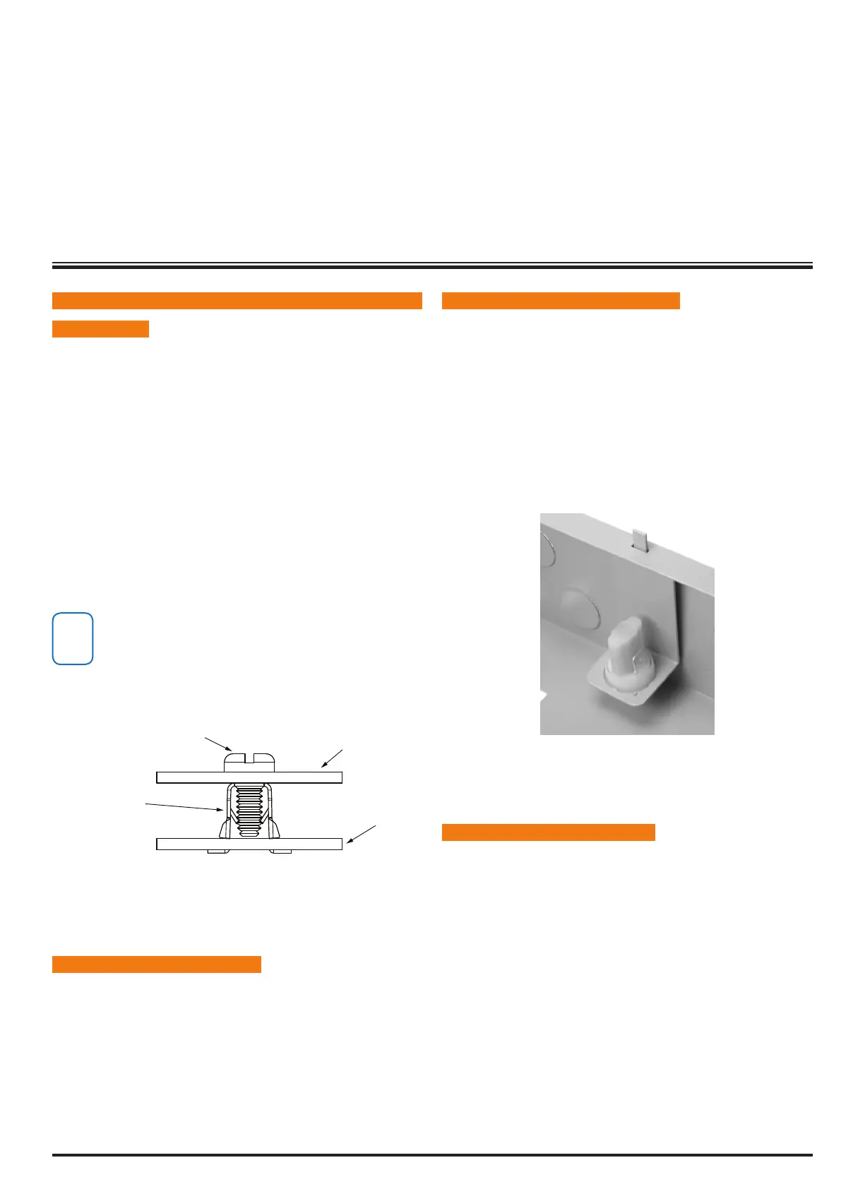
INS TA LL I NG TH E TA MPE R SW ITC H
The tamper switch can be located on either the left or right
hand side of the cabinet to suit the installation. Before installing
the bracket, t the tamper lead to the switch and then insert it
into the bracket.
Once the enclosure has been mounted to the wall, insert the
tamper bracket into the rectangular hole in the top ange of
the enclosure and then slide the base of the bracket toward the
top until the tamper switch locates in the rear of the enclosure.
Depress the tamper a few times with your nger to ensure
smooth operation.
Figure 2: Tamper Bracket Installation
ENC LOS URE MO DUL E S PAC ES
The MW700 enclosure has space for 2 large modules or 4 small
modules while the optional MW710 enclosure has space for up
to 4 large modules or 8 small ones. The enclosures have been
designed so that any combination of large and small units can
be neatly mounted together on the wall.
Each module is mounted to the enclosure using 4 or more
clip in standos. The clips can be inserted from the rear of the
enclosure before mounting it to the wall, or from the front of
the enclosure after it has been mounted. Both methods should
be performed using your nger tips to prevent damage to the
stando. (Standos and screws are supplied with each module).
All compatible add on modules will mount on these spaces. See
below for list if modules which can be added to the 64 control
panel.