8-9
Bosch Security Systems 05/10 BLCC100I
Solution 16
plus
Installation Manual Output Programming
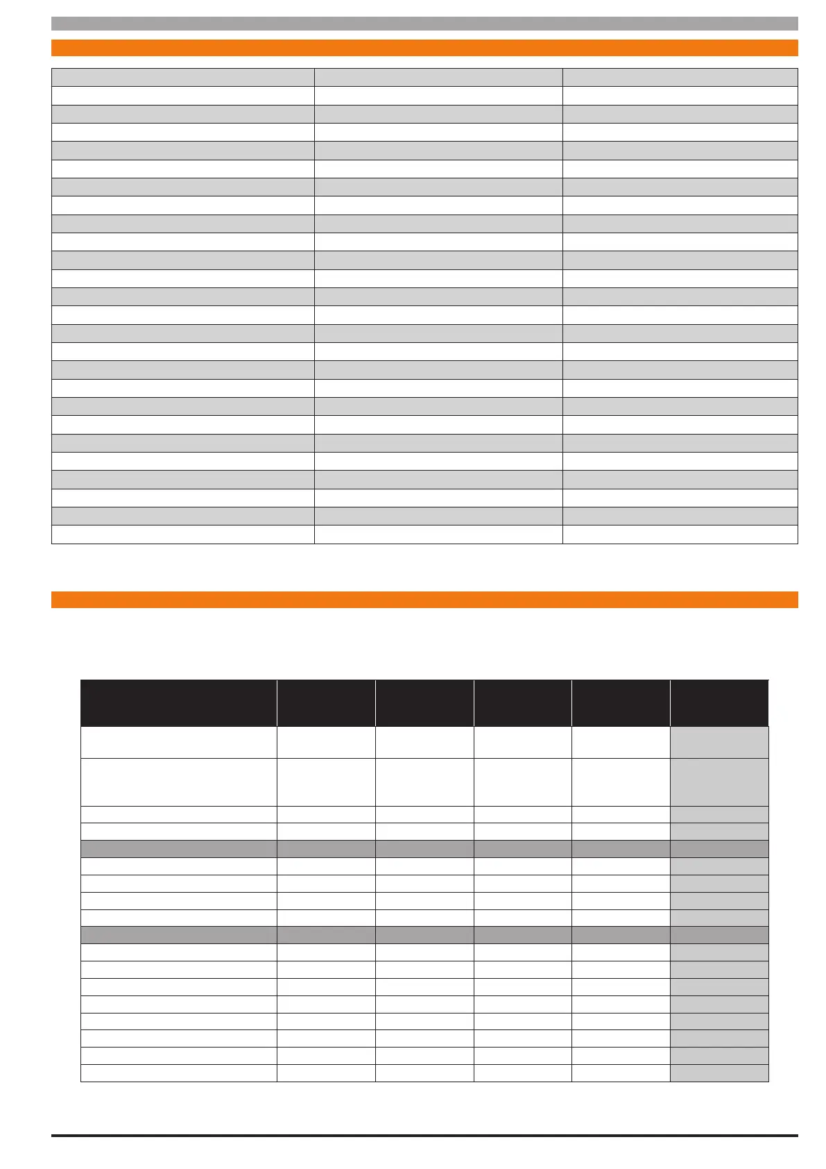
OUT PUT EV ENT T Y PE TAB LE
0 = Disabled
1 = Battery Trouble P 26 = Entry Time A 51 = Senior Watch A
2 = AC Trouble P 27 = Exit Time A 52 = Exit Error A
3 = Telephone Line Trouble P 28 = End Of Exit Time A 53 = RF Key Fob Function 1 A
4 = Comm Fail – Destination 1 / 2 P 29 = Chime On A 54 = RF Key Fob Function 2 A
5 = Third Dialler Attempt P 30 = Chime Zone Triggered A 55 = Output Pre- Alert A
6 = Destination 1 Reporting P 31 = Auto Arm Pre-Alert A 56 = Follow PIN Code U
7 = Destination 2 Reporting P 32 = Ready To Arm All On A 57 = Part Entry Time A
8 = Destination 1 or 2 Kiss O P 33 = Ready To Arm Part On A 58 = Time Schedule S
9 = Destination 1 Kiss O P 34 = Ready To Arm Part 2 On A 59 = Temperature Alarm K
10 = Destination 2 Kiss O P 35 = Closing Report Sent OK A 60 = Access Group G
11 = Dialler Disabled P 36 = External Siren (Spk Beeps) A
12 = Output Device Missing P 37 = Internal Siren A
13 = Output Trouble O 38 = Alarm Any (silent or Audible ) A
14 = Panel On Line P 39 = Fire Alarm A
15 = Incoming Call P 40 = Burglary Alarm A
16 = System Trouble P 41 = Silent Alarm A (A) = Area Event Assignment
17 = Box Tamper P 42 = Duress Alarm A (P) = Panel Event Assignment
18 = Zone Trouble Z 43 = Keypad Medical A (O) = Output Event Assignment
19 = Zone Mirror Z 44 = Keypad Fire A (Z) = Zone Event Assignment
20 = Zone Alarm Z 45 = Keypad Panic A (U) = User Event Assignment
21 = Area Disarmed A 46 = Device Tamper A (S) = Schedule Event Assignment
22 = Area Armed (Any) A 47 = Access Denied A (G) = Access Group Event Assignment
23 = Area All On A 48 = Strobe A (K) = Keypad
24 = Area Part On A 49 = Smoke Sensor GND A
25 = Area Part 2 On A 50 = Sensor Watch A
Table 25: Output Event Types
OUT PUT DE FAU LT TA B LE
The table below list the default values for all Output parameters in the Solution 16
plus
. Outputs 1 to 3 are High current digital outputs
and Output 4 is the onboard relay output. Outputs 5 to 8 are only available if the optional Output Relay Expander Boards (CM110)
are tted. Options marked N/A = Not Applicable.
Programming Option Output 1 Output 2 Output 3 Output 4 Output 5 to 8
Table 26: Output Default Table