4-4
Bosch Security Systems 05/10 BLCC100I
Solution 16
plus
Installation Manual Programming Overview
ZONE AR RAY
The feature allows you to view the condition of all zones on
the panel in banks of 16 zones at a time. From the installer
programing mode press MENU 3-0-1 to access the zone array.
Use the up and down arrow keys to scroll up and down the zone
banks and Press [OK] or [MENU] when nished.
The following information can be displayed depending on the
current zone status.
= NORMAL
= SHORTED
= ALARM
= TAMPER
= DISABLED
0000000001111111
1234567890123456
NSA-ANAT--------
PRESS
, OK or MENU
In the above example screen,
= Zone 01 and 06 are Normal (Sealed)
= Zone 02 is Shorted
= Zone 03,05,07 are in Alarm (Unsealed)
= Zone 08 is in Tamper Alarm (Unsealed)
= Zone 04, 09-16 are Disabled (Unused)
TES T IN G T H E SYSTE M
You will need to be in programming mode before accessing the
test functions listed below.
Walk Test
Use the walk test command MENU 3-9-0 to test and verify that
all zones work correctly.
External Audible Test
Use MENU 4-9-0 to test and verify that all horn speakers operate.
This test will sound the horn speaker for two seconds.
Internal Audible Test
Use MENU 4-9-1 to test and verify that all 12 VDC sirens operate.
This test will sound the siren for two seconds.
Strobe Test
Use MENU 4-9-2 To test and verify that the strobe operates. This
test will turn on the strobe until you manually stop the test.
Battery Test
Use MENU 7-9-1 to test the back-up battery that is connected to
the control panel.
Communication Test
Use MENU 5-9-0 to test the telephone reporting capability of
the control panel. You can also activate a communication test
by holding down the Test / Mail key on the keypad.
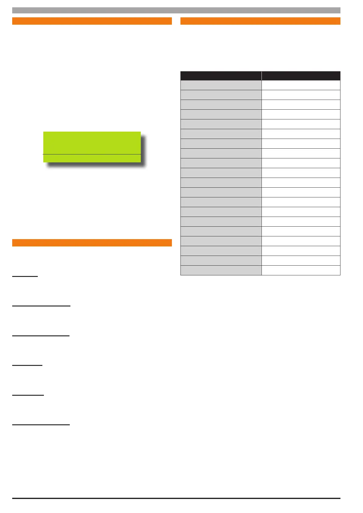
BAS IC REP OR T IN G R E FE R EN CE
The following table is a shortform point ID listing.
For a complete listing of all the CID and SIA event reporting
information that will be sent by the control panel you will need
to view the base station template document that is included on
the SolutionLink CD or contact your distributor.
Point ID Table Module Description
Ur999 Installer
Ur001 - 256 Users
Ur000 Quick Arm
Zn999 Keyfob Low Battery
Zn998 Keyfob Panic Alarm
Zn891-898 Panels 1-8
Zn881-888 Keypads 1-8
Zn871-878 Ethernet 1-8
Zn861-868 GSM 1-8
Zn851-858 Output Expander 1-8
Zn841-848 Serial Expander 1-8
Zn831-838 Lan P/Supply 1-8
Zn821-828 RF Reciever 1-8
Zn811-818 Access 1-8
Zn801-808 X10 1-8
Zn791-798 Lift 1-8
Zn001-128 Zones
Table 16: Shortform Point ID Listing