3-3
Bosch Security Systems 05/10 BLCC100I
Solution 16
plus
Installation Manual Wiring Diagrams
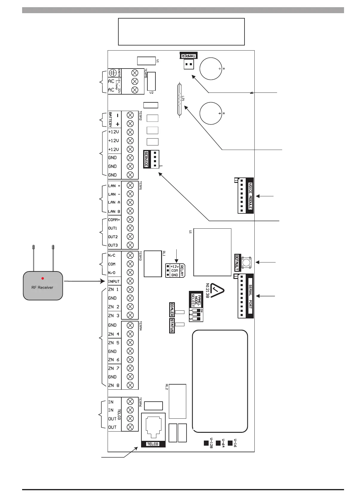
Figure 20: Terminal Descriptions
16-18 VAC
24VA
12VDC 7.2Ah
Sealed Lead
Acid Battery
Panasonic
LC-P127R2P or
Equivalent
Accessory
12 VDC Supply
(750mA Fused)
LAN Devices
Connection Terminals
(750mA Fused)
Output
Connection Terminals
500mA
Relay Output
Terminals
(2A @24 VDC)
RF Receiver
/ Keyswitch
Input
Zone Input
Terminals
Telephone Line
Connection
Terminals
Telephone Line
Connection Socket
(RJ12 6P4C)
Panel Cabinet
Tamper Circuit
Connection
Terminals
Battery
Charging
Globe
Voice Module
Connection Socket
(Optional)
4-Pin Socket
to LAN
Default /
Direct Connect
Switch
10-Pin Serial
Connection Socket
For Direct Link/
Flash Programming
ETC
Refer to
Documentation
For Dialer &
Status LED’s
Relay Output
COM Terminal
+/- Select PINS
The maximum continuous combined current
draw from the +12V, LAN + and COMM+
terminals must not exceed 1 Amp