© Copyright Brainboxes Ltd
Modbus 1.1b3 standard addressing
If you download the latest version (1.1b3) of the Modbus standard, you will find that it uses yet another
addressing style. In what it calls the “Modbus data model”, the address of each object starts at 1, i.e. it is the
logical address plus 1. You can see in the examples that the object addresses are always 1 greater than the
values actually transferred in Modbus data packets. Like the logical address, an address written this way does
not specify what is being addressed; the type of object/access needs to be stated as well.
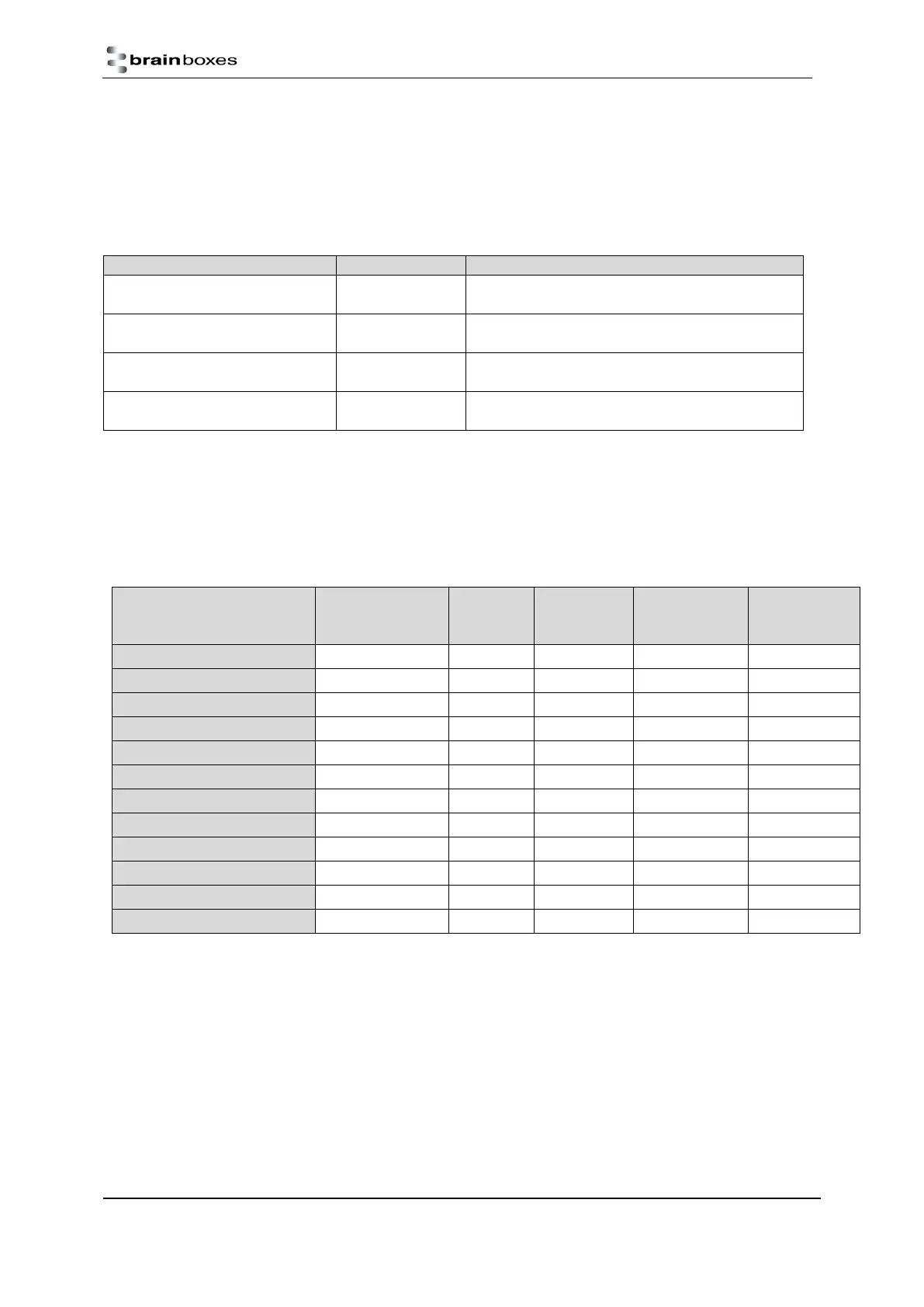
Modbus data model addresses
0x0000-0xFFFF (hexadecimal)
0x0000-0xFFFF (hexadecimal)
0x0000-0xFFFF (hexadecimal)
0x0000-0xFFFF (hexadecimal)
Despite being the latest official standard, this style of address notation is the least frequently seen in practice.
Product data tables and value encoding
ED-549
Analogue inputs (as integer)
Analogue inputs (as integer)
Analogue inputs (as float)
Analogue inputs (as float)
Integer values are encoded in one of two formats, depending on the integer format setting.
“Hexadecimal” (integer format register = 0, integer format coil OFF): the input range is scaled to fill
the range of a 16-bit integer value, either as a 2’s complement number for ranges which extend to
negative values or as an unsigned number for ranges which do not go below zero.
“Engineering units” (integer format register = 1, integer format coil ON): the measurement, in mA, mV
or V, is scaled up to as high a power of 10 as possible while allowing the full range of values to fit in a
16-bit integer. For example, the ±2.5V range is expressed as the reading in Volts multiplied by 10000:
if it were multiplied by 100000 then some values would be too large to fit in a 16-bit register.