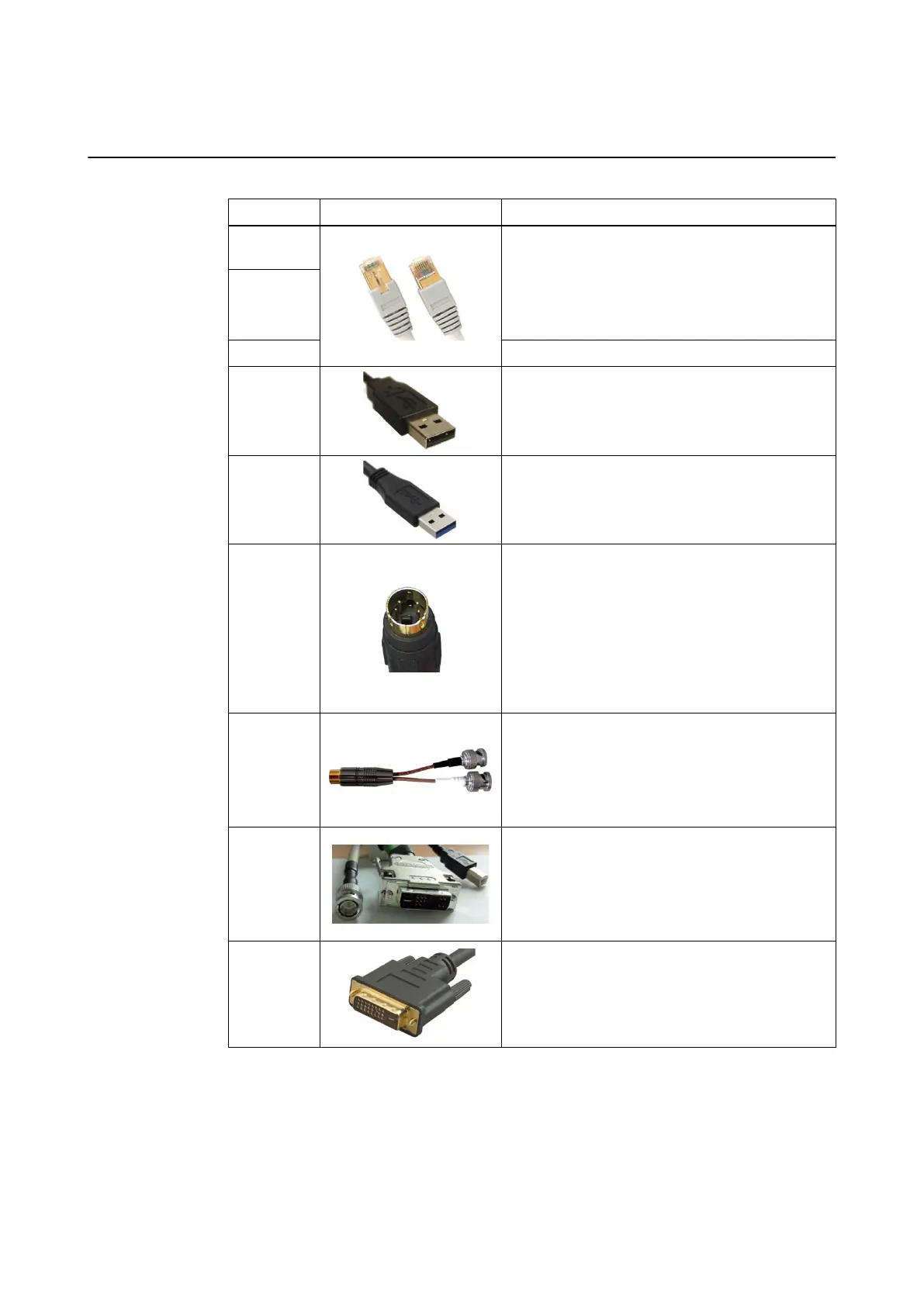
3.6.2 Back Panel Connections
Compatible Connection Cables
Port Example Handling
Hospital net-
work
Ethernet port for connecting to hospital network or
intraoperative data sources (min. Cat 5e RJ45 net-
work cable for max. 1 GB network).
There is a latch at the top which locks when plugged
into the port. When removing the connector, press
the latch, then pull plug out.
Intraopera-
tive data
Tracking unit Ethernet port for connecting a tracking unit.
USB 2.0
USB ports for connecting passive USB 2.0 devices
for patient data transfer.
USB 3.0 USB ports for connecting USB 3.0 devices.
S-Video In
To interact with Brainlab software video, connect S-
Video source with a 26 AWG miniature coaxial cable
(max. 5 m) with Mini-Din Hosiden plug to the Brain-
lab S-Video breakout cable.
Correctly align the plastic coding knob before plug-
ging in the cable. This connector cannot be locked.
Use Hosiden 4-pin Mini-DIN connectors only. Similar
connectors may appear to fit, but could lead to
equipment damage.
S-Video
breakout ca-
ble
Used for connecting S-Video sources to the Monitor
Cart.
Connect the black BNC connector to the S-Video In
Y port on the connection panel. Connect the white
BNC connector to the of the S-Video In C port on
the connection panel.
Microscope
Only connect microscopes via a Brainlab micro-
scope cable. Plug in the cable by connecting all
connectors (DVI-I, USB, CVBS) to the correspond-
ing port.
For detailed information on microscope integration
see the corresponding Instrument User Guide.
Video Out
Video out may also be used for the DVI connection.
NOTE: Brainlab does not provide this cable.
USING KICK 2
System and Technical User Guide Rev. 1.3 Kick 2 Navigation Station 39