6.4.3 Safety Inspection Form – Medical Electrical Systems
Tests to be Performed
Test Step Instructions and Conditions
Visual Inspection
• Check all relevant cables for dents, damaged isolation and blank lines.
Move and bend the cables around your hand to stretch the isolation
slightly. Any visible damage is not acceptable.
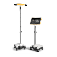
• Check Kick 2 for visible damage, broken cables and blank lines. With
the exception of air vents, you should not be able to see the interior of
the carts. Damaged cables, blank lines or visibility of the interior are not
acceptable.
• Ensure that Kick 2 is correctly assembled.
• If any damages are detected, place Kick 2 out of operation, mark as
such and contact Brainlab support.
Touch Current
• Connect the Monitor Cart and tracking unit and plug devices into
mains power supply using the original Brainlab mains power cable.
Connect all data connections for intended use.
• Place the device(s) that shall be connected into operating mode, as de-
scribed by the manufacturer of the device.
• Connect the required cable(s) to create the medical electrical system
and switch both devices on.
• Test the equipment touch current according to IEC 60601-1:2012 Chap-
ter 16.6.1 in normal condition and single fault condition. The interruption
of any non-permanently installed protective earth connection is consid-
ered single fault condition.
Functional test
• Power on the Kick 2.
• Load patient data and start a software application.
• Check that touchscreen interaction is accurate.
• Accurately track a Brainlab instrument.
• Verify the actual function of the created medical electrical system.
Report and evaluate
results
Generate a report and determine whether the device is safe and effective.
Check and prepare
for normal use
• After testing, check that Kick 2 is restored to the conditions necessary
for normal use before being returned into service.
• Remove all devices that have been connected (e.g., measurement
lines).
Critical Values
Test Step Normal Condition Single Fault Condition
Touch Current
≤
0.1 mA
≤
0.5 mA
Reference Dimension
Enter the maximum measured value at each required measurement point in the table below:
Test Step
Normal Condi-
tion
Single Fault
Condition
Passed?
Touch current
Serial number of measuring device: ________________________
Calibration valid through (date): ________________________
Safety Inspection Form – Medical Electrical Systems
76 System and Technical User Guide Rev. 1.3 Kick 2 Navigation Station