4-42 100-214-276 Rev. 3
Chapter 4: Installation and Setup
Testing the Installation
4.10 Testing the Installation
1. Turn on the air supply connections including the pneumatic dump valve and verify that the air pres-
sure indicator light in the actuator is lit.
2. Ensure there are no leaks in the air supply connections.
3. Turn on the power supply. The power supply will begins its normal self-check.
4. If the power supply displays an alarm message other than Recalibrate Actuator, find the alarm
message definition, cause and correction in Chapter 7 of this manual. If the power supply displays
the alarm message Recalibrate Actuator, or “Ready” appears in the power supply display, go on to
the next step.
5. Perform an actuator calibration by touching the Main Menu button, and then touch the Calibration
button. Verify that there is a minimum clearance from horn face to workpiece greater than 0.70".
6. Touch Cal Actuator.
7. In the screen that follows, touch w/Start Switches (Automation users select Manual Override).
8. Press the Start switches to complete the calibration.
9. Press the Test button.
10. If the power supply displays an alarm message at this point, find the alarm message definition in
the Maintenance section of Chapter 7 of the power supply manual. If there are no alarm messages
displayed, go on to the next step.
11. Fit a test part onto the fixture.
12. Touch Horn Down on the Main Menu. The horn will descend to the fixture on the base of the Actu-
ator. This verifies specifically that the pneumatic system is
working.
13. Press the Retract button or any of the 4 buttons on the bottom row. The horn will retract. The sys-
tem should now be functional and can be set up for your application.
In summary, if the power supply does not display an alarm message and the descends and retracts cor-
rectly, your ultrasonic welder is ready for operation.
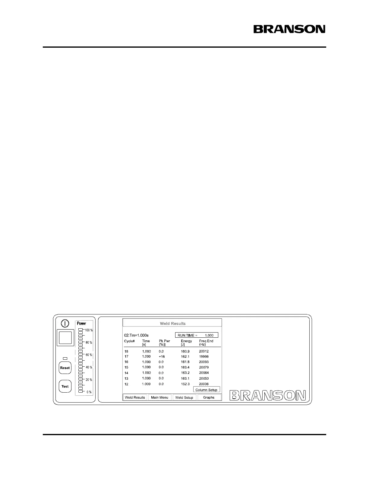
Figure 4.28 Normal Front Panel Display After Power-Up
DOC EXPIRES 12PM 7/24/2012. Article or Material must comply with the requirements
stipulated by RoHS in its current version