100-214-276 Rev. 3 4-41
2000X aed Actuator Chapter 4: Installation and Setup
Instruction Manual Mounting the Fixture on the Branson Base
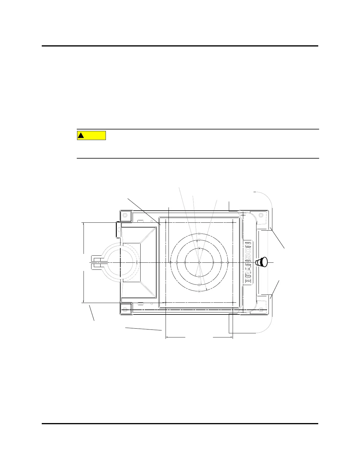
4.9 Mounting the Fixture on the Branson Base
(hardware and mounting holes)
The base provides mounting holes for your fixture. Mounting holes are also provided for the optional Bran-
son leveling plate kit. The base is tapped for metric M10-1.5 hardware (indicated by an “M” on the base).
The mounting holes are arranged in three concentric bolt circles with the following dimensions.
The base is cast metal and the mounting holes can become stripped if the hardware is over-
tightened. Tighten your hardware only enough to prevent movement of your fixture.
Figure 4.27 Mounting Circles on Base
The optional guard, EDP 101-063-550, (sometimes required with very large horns) is shown for position
only. It extends several inches to either side of the base, and prevents the user from operating the welder and
pinching their fingers or hands between the base and the tooling.
9.00 in / 229mm
7.00 in / 178 mm
4.44 in / 113 mm
M = metric M10 hardware
10.50 in
287 mm
12.50 inch
317.5 mm
Optional
Guard
shown for
position only
Leveling Plate
mounting dimensions
DOC EXPIRES 12PM 7/24/2012. Article or Material must comply with the requirements
stipulated by RoHS in its current version