4-30 100-214-276 Rev. 3
Chapter 4: Installation and Setup
Installation Steps
4.5.13 User I/O DIP Switch (SW1)
DIP switch SW1 for the user I/O is located next to the J3 on the back of the 2000X-series power
supply. The settings of these switches affect the user I/O signals. Factory default setting is with all
dip switches set to ON (switch position closest to number designation).
• If the dip switch is set to the ON (closed) position, the corresponding Output pin will be configured as
the current source, 25mA max, Active low, Logic 1=24VDC, Logic 0=0VDC.
• If the dip switch is set to the OFF (open) position, the corresponding Output pin will be configured as an
“open collector”, 24VDC, 25 mA max. current sink.
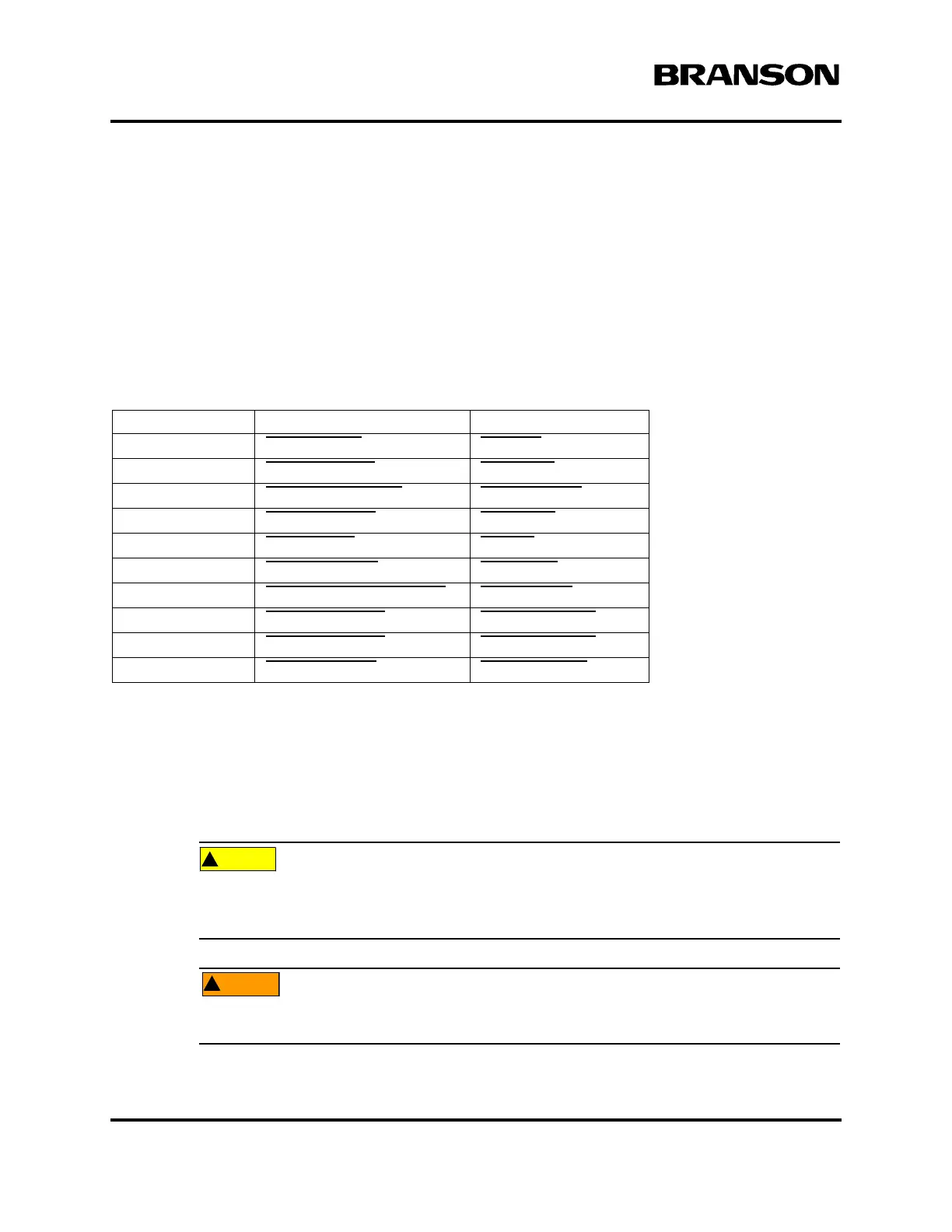
Table 4.8 User I/O DIP Switch Functions
4.5.14 Module Options DIP Switch
In some configurations, it might be necessary to open the Power Supply and change the DIP (Dual In-line
Package) switches on the power supply module. DIP switches change the Seek and Start functions and can
affect the Amplitude Control functions. Refer to your Power Supply Instruction manual, or 2000X Series
Installation Guide for detailed information.
The components in the Power Supply are subject to damage from electro-static discharge.
When working inside the Power Supply, use a grounded wrist strap and minimize your move-
ment to reduce the possibility of damage due to static electricity.
Unplug the Power Supply (if previously connected) and wait at least two (2) minutes before
opening the Power Supply case. Hazardous Voltages exist and are stored in the system.
Switch Position Signal Description Output Signal
1 REJECT_SIG REJECT
2 SUSPECT_SIG SUSPECT
3 PB_RELEASE_SIG PB_RELEASE
4 G_ALARM_SIG G_ALARM
5 READY_SIG READY
6WELD_ON_SIG WELD_ON
7 ACTUATOR_CLEAR_SIG ACT_CLEAR
8 J3_22_OUT_SIG J3_22_OUTPUT
9 J3_36_OUT_SIG J3_36_OUTPUT
10 J3_8_OUT_SIG J3_8_OUTPUT
DOC EXPIRES 12PM 7/24/2012. Article or Material must comply with the requirements
stipulated by RoHS in its current version