4-26 100-214-276 Rev. 3
Chapter 4: Installation and Setup
Installation Steps
The printers listed in Table 4.5 have been fully tested to confirm compatibility with Branson products. Print-
ers that were tested and are NOT compatible are the Panasonic 1091 and Epson LX300. The printer inter-
face uses a standard 36-pin Centronics cable (Branson printer cable EDP 100-143-043).
** Includes both off the shelf and Branson supplied units. However, all units excepting the Branson supplied
Okidata 520 may not stop printing when abort is selected in the menu. The data may have been transferred
to the printer and can’t be halted.
Power for the Power Supply and the printer must be OFF before installing the printer cable.
If it is installed with power on, the power supply front panel may lock up.
4.5.11 User I/O Interface
The user I/O is a standard interface for automation, provided on the power supply. It provides the ability for
the customer to make their own interface for their automation or special control or reporting needs. The
interface cable has an HD44 female D-shell connection on the rear of the power supply. The electrical inter-
face outputs may be configured for open collector mode or for signal mode (signal voltage levels as indi-
cated), by setting the user I/O DIP switch.
DIP switch SW1 for the user I/O is located next to the J3 on the back of the 2000X-series power supply.
User I/O interface cable pinout is listed in Table 4.6
.
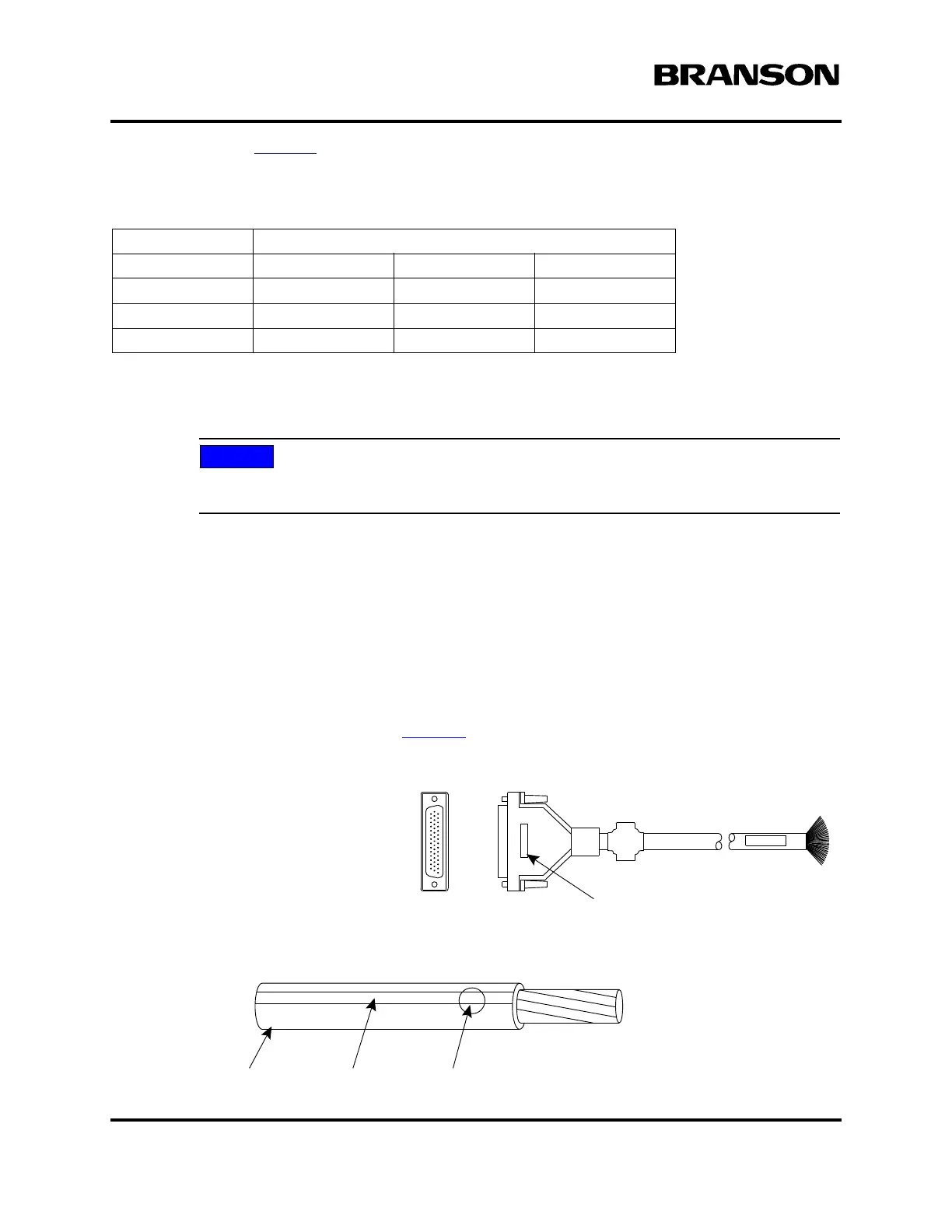
Figure 4.18 User I/O Cable Identification and Wire Color Diagram
Table 4.5 Printer Compatibility
Manufacturer Model No
Epson LQ-570 FX-980 Stylus 900
Okidata 5340HE 320 Turbo 520**
Panasonic 1180 1150
H-P 610C 540 600
User I/O Cable
Stripped and tinned one end,
HD-44 male connector other end
(cable length as ordered)
Part number
Wire Color Diagram
Two Colors = Insulator/Stripe
Three Colors = Insulator/Stripe/Dot
Insulation Stripe Dot
DOC EXPIRES 12PM 7/24/2012. Article or Material must comply with the requirements
stipulated by RoHS in its current version