2/24/2008 9T6WP
Preliminary Hardware Data Module BCM7405
06/29/07 Timing and AC Characteristics
Broadcom Corporation
Document 7405-1HDM00-R EBI Timing Page 1-161
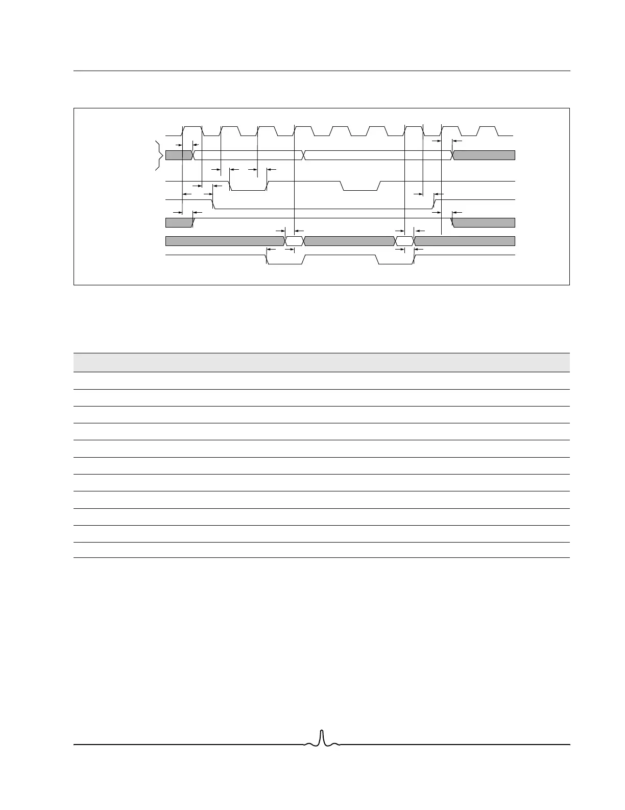
SYNCHRONOUS READ TRANSFER
Figure 1-46: Synchronous Read Timing Diagram
Table 1-32: Synchronous Read Timing Parameters
Description Symbol Min Max Units
Delay time: EBI_CLK rising to EBI_ADDR[23:0] valid t
1
311ns
Delay time: EBI_CLK rising to EBI_ADDR[25:24] or EBI_TSIZE[1:0] valid t
1
313.5ns
Delay time: EBI_CLK rising to EBI_TSb low or high t
2
313ns
Delay time: EBI_CLK rising to EBI_CSb[n] low or high (CSHold=0) t
3
313.5ns
Delay time: EBI_CLK falling to EBI_CSb[n] low or high(CSHold=1) t
4
313.5ns
Delay time: EBI_CLK rising to EBI_RWb low or high t
5
313ns
Setup time: EBI_DATA[15:0] valid to EBI_CLK edge t
6
7–ns
Hold time: EBI_DATA[15:0] valid after EBI_CLK edge t
7
0–ns
Setup time: EBI_TAb valid to EBI_CLK edge t
8
7–ns
Hold time: EBI_TAb valid after EBI_CLK edge t
9
0–ns
Note:
Load is 35 pF for all EBI pins.
Data Data
t
1
t
2
t
3
t
2
t
5
EBI_CLK
EBI_ADDR[25:0]
EBI_TSIZE[1:0]
EBI_TSb
EBI_CSb[n]
EBI_RWb
EBI_DATA[15:0]
EBI_TAb
t
5
t
4
t
7
t
6
t
8
t
9
t
4
t
1
t
10
t
11