2/24/2008 9T6WP
BCM7405 Preliminary Hardware Data Module
Functional Description 06/29/07
Broadcom Corporation
Page 1-76 Peripherals Document 7405-1HDM00-R
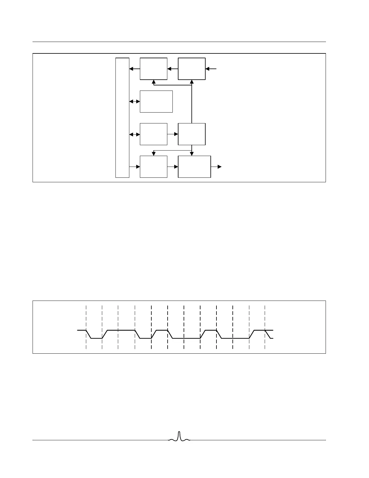
Figure 1-22: UART Functional Block Diagram
Functional Description
Asynchronous Communications Encoding
The UART handles standard asynchronous NRZ encoded format with seven or eight bits/characters, one stop bit/character,
and even, odd, or no parity. Figure 1-23 shows the waveform when eight bits of data and even parity are transmitted.
Generally, a start bit (a Low for 1 bit interval) starts the sequence. This is followed by seven or eight data bits, 0 or one parity
bit and one stop bit (a High for 1 bit interval). The start bit for a data sequence may immediately follow the stop bit of the
previous sequence.
In NRZ data encoding, a 1 is represented by a high level for the bit interval and a 0 is represented by a low level for the bit
interval.
Figure 1-23: Asynchronous Serial Data Waveform (01001011 Data, 8-bit Character, Even Parity)
Receiver
Receive
Data
FIFO
Control and
Status
Registers
Baud
Rate
Register
Baud
Rate
Generator
Transmit
Data
FIFO
Transmitter
Processor Interface
TXD
RXD
Data
Bit 1
1
Data
Bit 2
0
Data
Bit 3
1
Data
Bit 4
0
Data
Bit 5
0
Data
Bit 6
1
Data
Bit 7
0
Parity
Bit
0
Stop
Bit
Start
Bit
Data
Bit 0
1