2/24/2008 9T6WP
BCM7405 Preliminary Hardware Data Module
Functional Description 06/29/07
Broadcom Corporation
Page 1-82 Peripherals Document 7405-1HDM00-R
M-CARD CPU INTERFACE
Introduction
MCIF is the CPU interface controller for the Multi-Stream CableCARD and is illustrated in Figure 1-26. The physical interface
is a modified SPI (Serial Peripheral Interface). The data changes on the falling edge of the clock (SCLK, 6.75 MHz) and
clocked in on the rising edge. A control signal (SCTL) is utilized to signal the start of a byte of data as well as the start of a
new packet. There are separate data signals: SDI and SDO. Basically, SDI is data going into the MCIF and SDO is the data
coming out.
When the start of a packet occurs, the first byte is defined as the interface query byte, which includes the interface flags.
After the interface query byte, the packet count consists of two bytes which contain the number of data bytes in the packet.
The maximum number of data bytes in a packet is 4096.
See the CableCARD Interface specification’s section 4.1.7 CPU Interface for more details. The specification can be found at:
http://www.opencable.com/downloads/specs/OC-SP-MC-IF-I01-030905.pdf
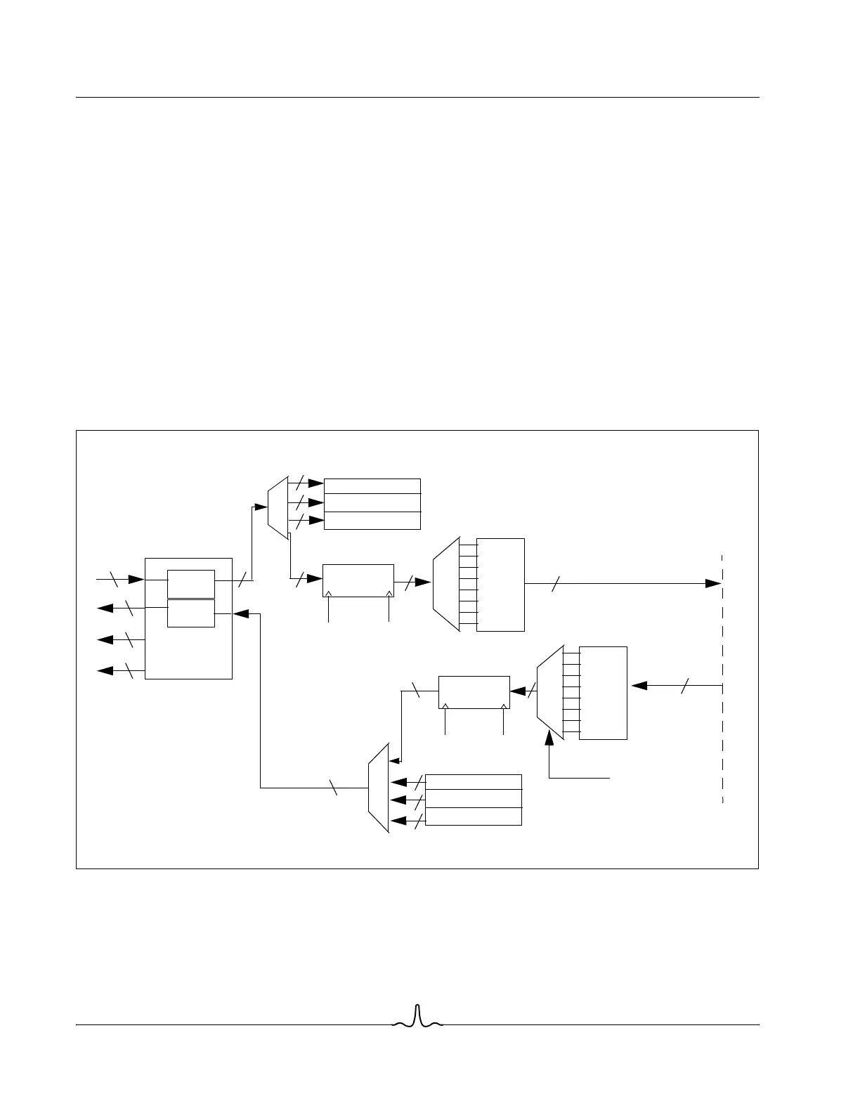
Figure 1-26: M-Card CPU Interface
Figure 1-27 illustrates the interfaces of the M-Card CPU Interface.
32x8 FIFO
8
IQB
MSB
LSB
256
clk_108
32x8 FIFO
clk_6p75
256-bit
8
8
8
8
Memory Interface
register
Byte Select
256
1
SDI
1
SDO
1
1
SCK
SCTL
8
8
8
8
8
8
S2P
P2S
IQB
MSB
LSB
Data Path
8
clk_6p75 clk_108
256-bit
register