2/24/2008 9T6WP
BCM7405 Preliminary Hardware Data Module
Functional Description 06/29/07
Broadcom Corporation
Page 1-72 Peripherals Document 7405-1HDM00-R
encoding. A programmable noise filter, located before the decoders, can be configured to filter out narrow spikes and
glitches.
IR BLASTER CONTROLLER
The IR blaster controller takes data sent from the microcontroller and loads it into the blaster's control logic. The data is
converted into a coded format compatible with the user's VCR or handheld remote display. The coded data is passed from
the chip to the IR transmitter where it is sent to the VCR or remote display via infrared light.
The IR blaster has been designed to transmit one entire IR keystroke consisting of up to 160 pulse sequences. Up to 80
pulse sequences can be transmitted without processor intervention. The IR blaster also provides the capability of repeating
the same blast sequence up to 256 times without processor intervention. The output of the IR blaster logic is a single-bit
pulse stream. This stream is then converted to infrared light by an external IR emitter.
The IR blaster provides support for two types of IR transmission:
• IR Flash—This modulation scheme is baseband Pulse-Width modulated (PWM).
• IR Carrier—This modulation scheme is the same as flash IR, except that a fixed-frequency square-wave carrier is
modulated by the baseband PWM pulse sequences.
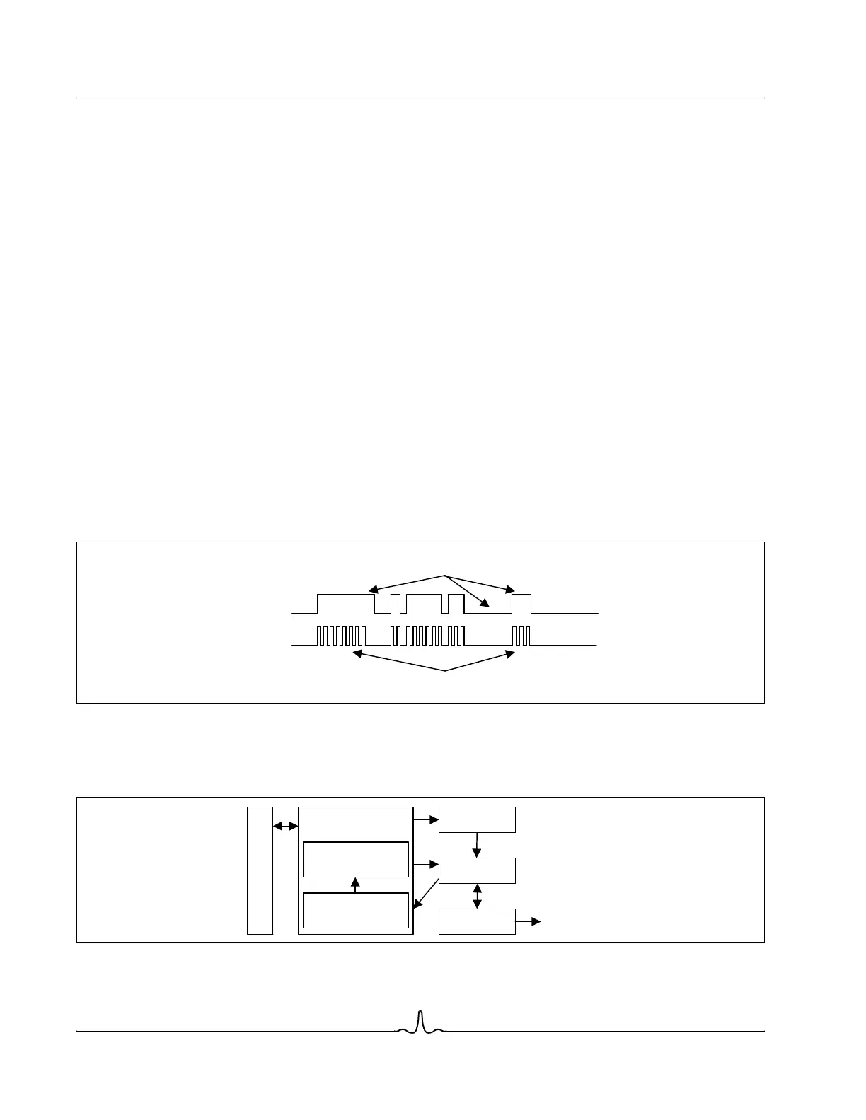
Flash IR is pulse width modulation without a carrier. Carrier IR is similar to Flash IR with the exception that a carrier is
modulated by the pulse widths in the Flash IR scheme. Figure 1-18 shows an example of a Flash IR scheme. The IR blaster
generates a binary sequence on IROUT. This binary sequence is then converted to infrared light and transmitted to a device
capable of receiving this signal.
Figure 1-18: Flash IR Scheme Example
Figure 1-19 shows a high-level, simplified block diagram of the IR Blaster.
Figure 1-19: IR Blaster Block Diagram
Flash IR
Carrier IR
Programmable Carrier Frequency and Duty Cycle
Programmable Modulating Pulse Widths
IRB Clocks
IRB Counts
IRB States
IRB Registers
14x16 Modulating
Register File
40x8 Sequencing
Register File
Processor Interface
IR Out