114 Brocade MLX Series and NetIron XMR Hardware Installation Guide
53-1002373-02
Installing a Brocade MLXe-32 router
2
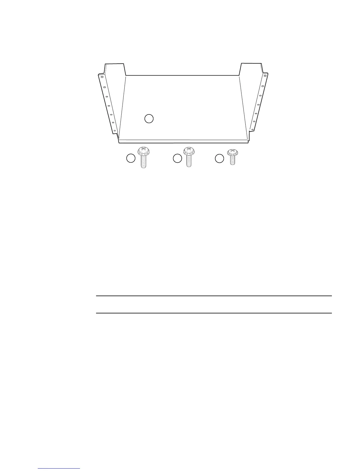
FIGURE 79 Open Frame EIA 310-D Rack Mount Kit contents
2. Allow 35U in the rack to accommodate the router. See Figure 80 for alignment:
• The saddle requires 1U of permanent space in the rack.
• The router requires 33U of space in the rack, plus 1U temporary space above for
installation.
3. Align the holes in the saddle with the holes on the mounting posts and attach the saddle using
a minimum of eight standard pan head screws that were provided in the kit, either #12-24,
#10-32, or M6, as appropriated for your rack (four screws on each post, in the three top holes
and one bottom hole). See Figure 81.
Additional screws may be used for more support.
1Saddle
2 10-32 x 5/8 inch screw
3 12-24 x 1/2 inch screw
4 M6 x 12 mm screw
 Loading...
