Brocade MLX Series and Brocade NetIron XMR Hardware Installation Guide 165
53-1002373-02
Installing a Brocade MLX-8 router
3
Unpacking a Brocade MLX-8 router
The Brocade MLX-8 router ships with the following items:
• Switch fabric modules installed in slots marked SF, and slot blanks installed in all empty
module slots.
• Insertion or extraction tool for use with RJ45 and fiber-optic connectors.
If any items are missing, contact the place of purchase.
Save the shipping carton and packing materials in case you need to move or ship the router at a
later time.
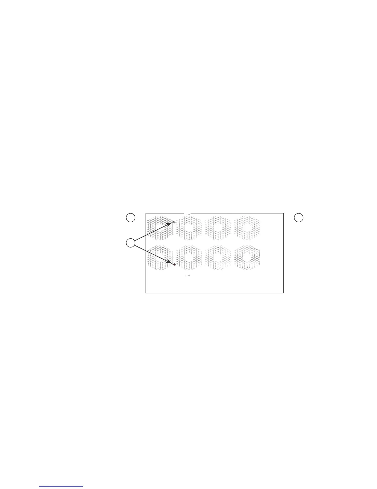
Removing the shipping screws
The router ships with two screws installed in the right side of the router. These screws secure the
fan tray and protect it from damage during shipment. You must remove these screws before
installing the router. Figure 117 shows the location of these screws.
You will need a #2 Phillips screwdriver to remove these screws.
FIGURE 117 Removing the shipping screws
Lifting guidelines for Brocade MLX-8 routers
Follow these guidelines for lifting and moving Brocade MLX-8 routers:
• Before lifting or moving the router, disconnect all external cables.
• Do not attempt to lift a fully configured router by yourself.
• It is recommended that you install router components after you have installed the router in a
rack.
Installing a Brocade MLX-8 router in a rack
You can install up to six Brocade MLX-8 routers in a standard 19-inch (EIA310-D) rack. You can
install the routers in either a front-mount configuration (using the factory-installed mounting
brackets) or a mid-mount configuration. For a mid-mount configuration, simply remove the
factory-installed mounting brackets from the front edges of the device and re-attach them to the
center sides of the device using the pre-drilled holes.
1 Front 2 Rear 3 Shipping screws
 Loading...
