254 Brocade MLX Series and NetIron XMR Hardware Installation Guide
53-1002373-02
Installing a Brocade NetIron XMR 8000 router
4
Installing the Brocade NetIron XMR 8000 router in a rack
Because of the weight of a fully loaded Brocade NetIron XMR 8000 router, Brocade recommends
mounting the router in a rack before installing the modules and AC power supplies.
You can install up to six Brocade NetIron XMR 8000 routers in a standard 19 in. (EIA310-D) rack.
You can install your devices in a front-mount or mid-mount configuration using the factory-installed
mounting brackets. For a mid-mount configuration, simply remove the factory-installed brackets
from the front edge of the device and re-attach them to the center sides of the device using the
pre-drilled holes.
For each Brocade NetIron XMR 8000 router you install in a rack, you must provide four standard
#12-24 pan-head screws to secure the router. Before performing this task, you should have an
assembled rack and a #2 Phillips-head screwdriver.
Follow these steps to mount a Brocade NetIron XMR 8000 router in a rack.
1. Determine the position of each router in the rack. For example, install routers with the fewest
modules near the top of a rack, routers with more modules near the middle of the rack, and
fully populated routers near the bottom of the rack.
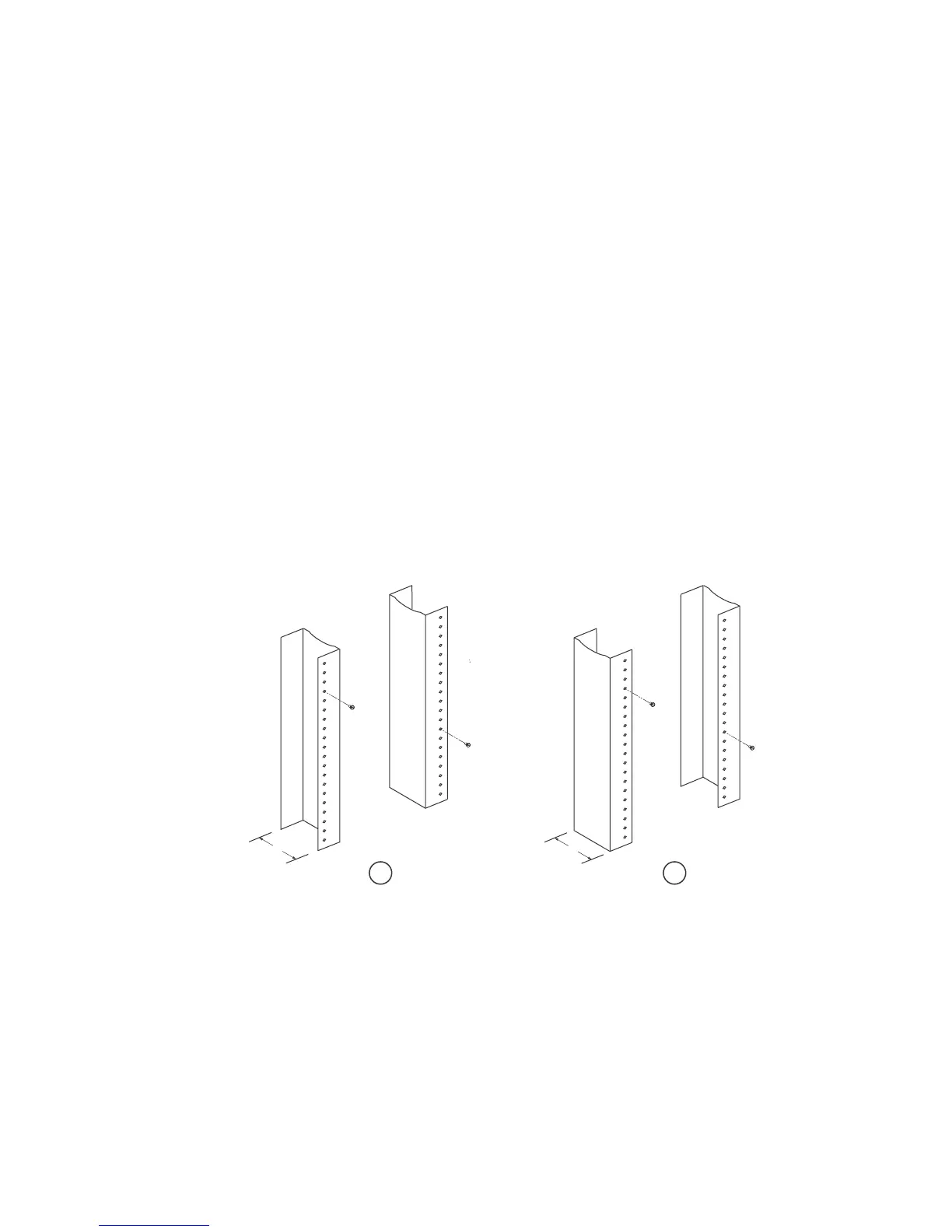
2. Position two of the four mounting screws for each router according to the spacings of the
keyhole slots on the mounting brackets, as shown in Figure 177. When tightening the screws
leave approximately 1/4 inch clearance between the back of the screw head and the rack post.
FIGURE 177 Positioning the screws in a rack
3. Starting at the bottom of the rack, mount the router in the rack as shown in Figure 178. Slip
the wide portion of each keyhole slot over the corresponding screw in the rack.
1 Unequal flange equipment rack 2 Network equipment rack
 Loading...
