Brocade MLX Series and Brocade NetIron XMR Hardware Installation Guide 295
53-1002373-02
Installing a Brocade NetIron XMR 32000 router
4
To ensure adequate bonding when attaching the ground lug, a minimum of 20 PSI of torque is
required to be applied to the mounting hardware used to attach the ground lug.
FIGURE 209 Crimping the power supply wire in the lug
4. Reconnect the power lugs to the power supply unit.
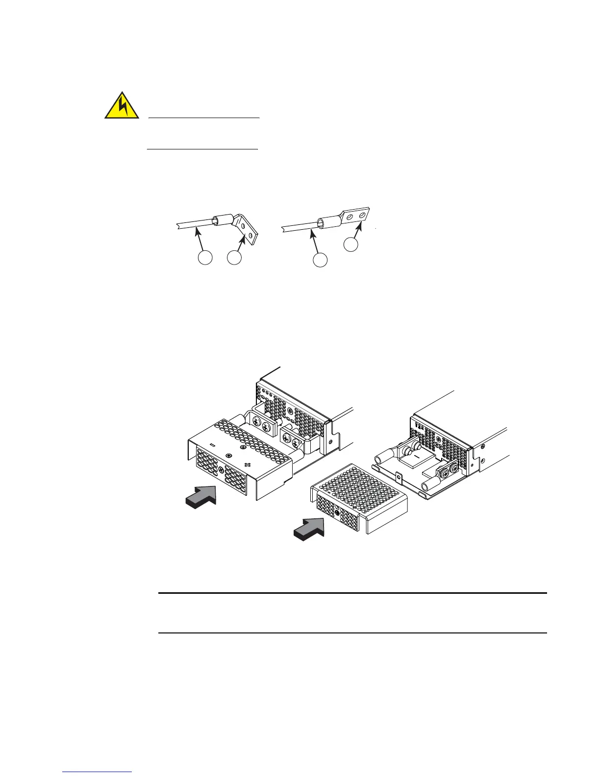
5. Replace the safety cover. Refer to Figure 210.
FIGURE 210 Attaching the safety cover
6. Connect the wire to your DC power source, making sure to connect the -48V cable to the
negative terminal on the power supply and the 0V cable to the positive terminal as marked on
the power supply.
DC return must be isolated from the device ground (DC-I) when connecting to the power
supply.
This equipment installation must meet NEC/CEC code requirements. Consult local authorities for
regulations.
1 #4 AWG power supply wire 2 Power lug
 Loading...
