Brocade MLX Series and Brocade NetIron XMR Hardware Installation Guide 81
53-1002373-02
Installing a Brocade MLXe-8 router
2
You can install up to six Brocade MLXe-8 routers in a standard 19-inch (EIA310-D) rack using the
standard rack installation method. If you use the cabinet mounting kit, you can install up to 4
Brocade MLXe-8 routers in a standard 19-inch rack.
Front- or mid-mount your device in a standard rack
Your Brocade MLXe-8 router ships from the factory with mounting brackets attached for
front-mount installation in a standard 2-post rack. You can also use these brackets for a mid-mount
installation by simply removing the brackets from the front edges of the device and re-attaching
them in the center sides of the device using the pre-drilled holes. Refer to Figure 53.
You will need to provide four standard #12-24 pan-head screws (per router) and a #2 Phillips
screwdriver to secure routers in the rack.
If you are installing your Brocade MLXe-8 router in a cabinet or 4-post rack, refer to “” on page 146.
When connecting the device to the rack frame, use thread-forming screws and paint-piercing
washers.
Follow these steps to mount your device in a standard 2-post rack in either a front- or mid-mount
configuration.
1. Determine the position of each router in the rack according to weight. For example, mount the
router with the fewest modules near the top of the rack, the router with more modules near the
middle of the rack, and a fully populated router near the bottom of the rack.
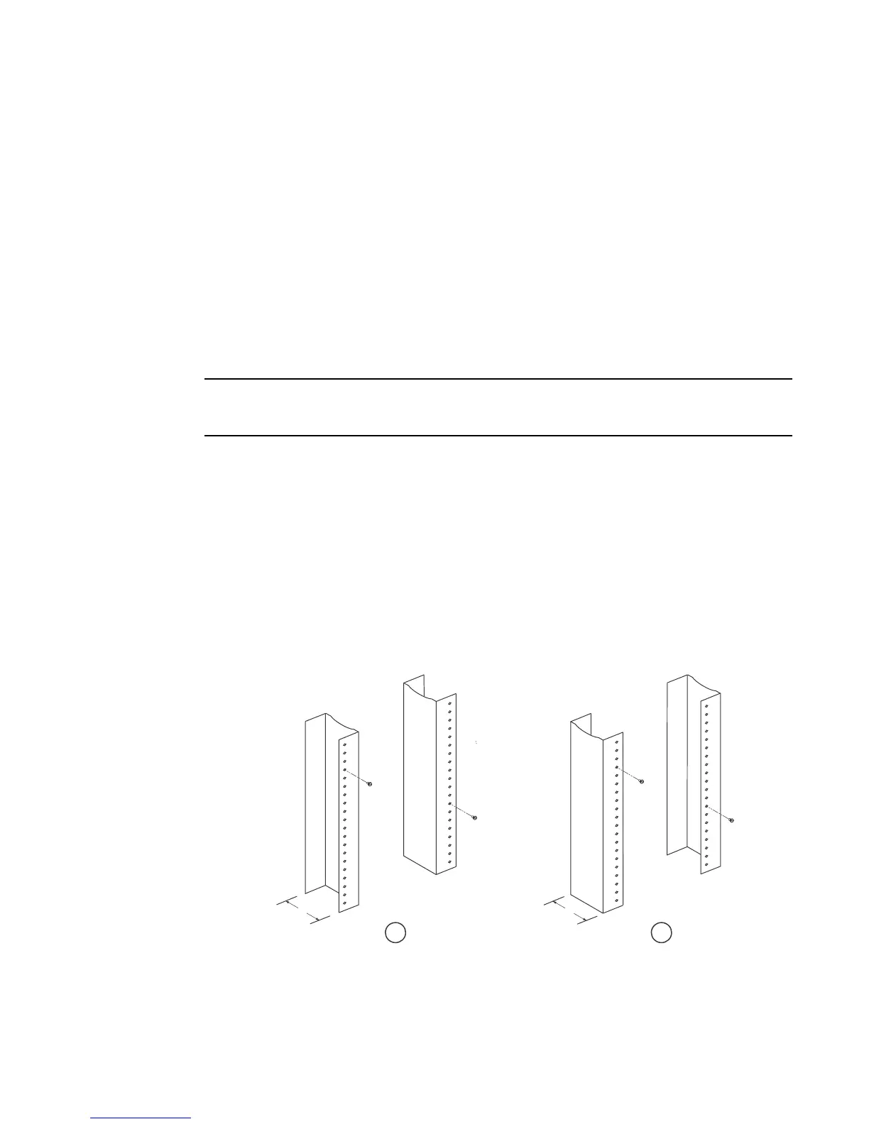
2. Using the keyhole slots in the router mounting brackets as a guide, align one screw per rack
post, as shown in Figure 52. On one side of the rack, the screw should align with the top hole in
the mounting bracket. On the other side of the rack, the screw should align with the bottom
hole of the mounting bracket. When tightening these screws, leave approximately 1/4 inch of
clearance between the back of the screw head and the rack post.
FIGURE 52 Positioning the mounting screws in rack posts
1 Unequal flange equipment rack 2 Network equipment rack
 Loading...
