3-54
Confidential
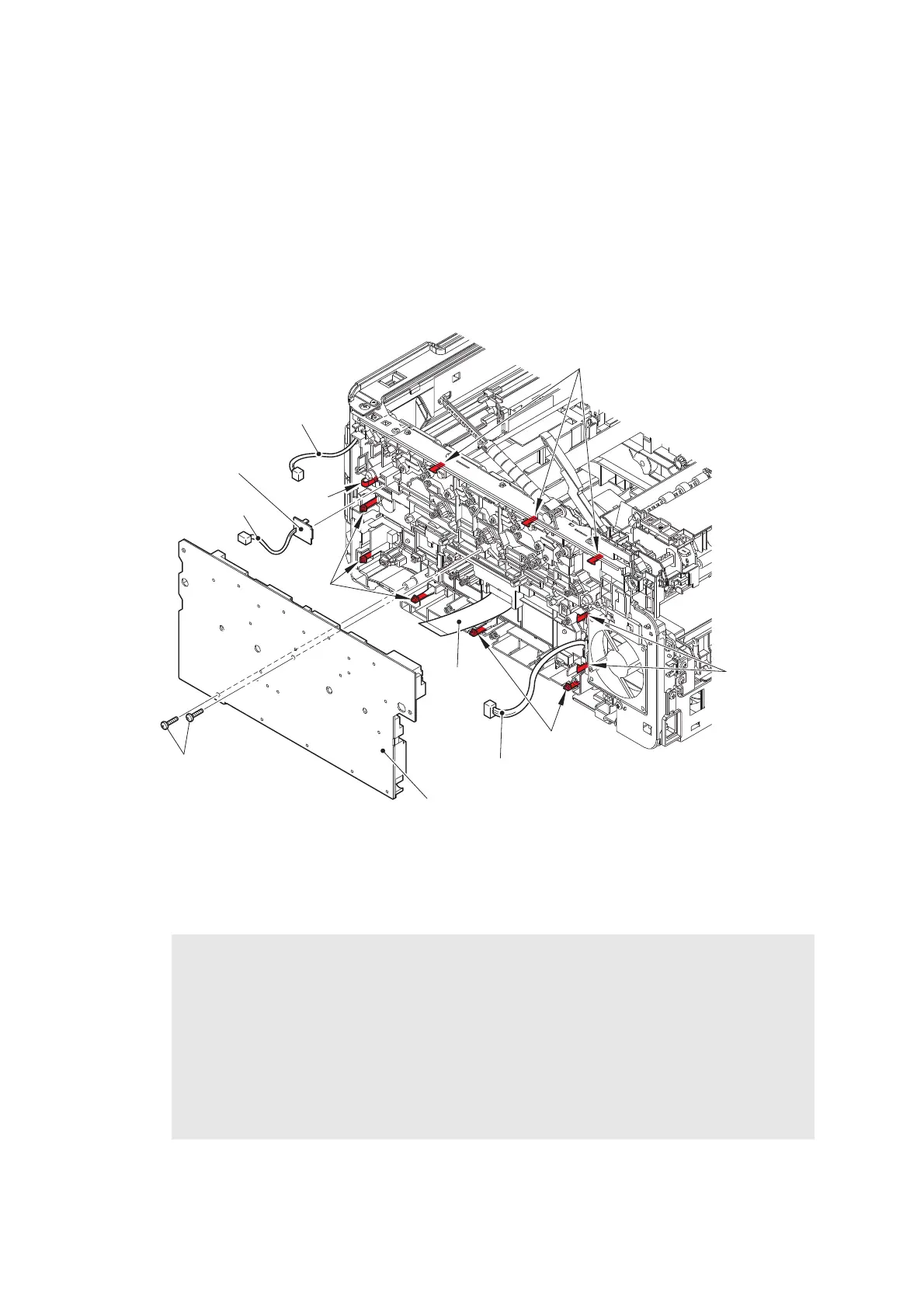
(5) Release the High-voltage power supply flat cable from the securing fixtures inside the
machine and extend the folds. Remove the two Taptite bind B M4x12 screws. Release
each Hook to remove the High-voltage power supply PCB. Disconnect the HVPS
harness, the Develop release sensor harness, and the Fan harness from the High-voltage
power supply PCB. Disconnect the High-voltage power supply flat cable from the High-
voltage power supply PCB.
(6) Release the Hook to remove the Develop release sensor PCB.
Fig. 3-45
Harness routing: Refer to “3. High-voltage power supply PCB, Fan harness, LED ground
wire”.
Assembling Note:
• After attaching the High-voltage power supply PCB, check whether the Electrodes inside
the machine are not dropping or not get caught by pushing the Electrodes inside the
machine.
• When connecting the High-voltage power supply flat cable, pull out the High-voltage
power supply flat cable from the machine and then connect it to the High-voltage power
supply PCB. Then, attach the High-voltage power supply PCB to the machine while
pulling the High-voltage power supply flat cable to the machine side (Refer to “5. High-
voltage power supply flat cable”.)
Hooks
Hooks
Hooks
High-voltage power supply PCB
Taptite bind
B M4x12
Hooks
Develop release
sensor PCB
Hook
Fan harness
Develop release
sensor harness
HVPS harness
High-voltage
power supply
flat cable
 Loading...