2-80 2002 Buell X1: Chassis
HOME
ASSEMBLY
1. See Figure 2-132. Slide license place bracket (9) over
tail section (14).
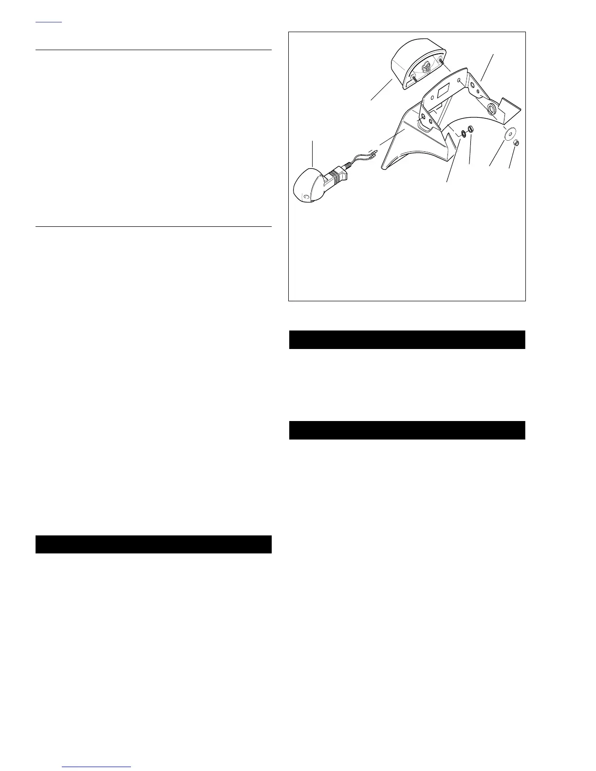
2. See Figure 2-133. Install turn signals (1), with drain
holes facing down, with star washers (7) and nuts (6)
(metric). Tighten to 96-120 in-lbs (11-14 Nm). See
7.13
TURN SIGNALS to connect wiring.
3. Install nuts (metric) (4) and washers (5) for tail lamp (2).
Do not connect wires until after installation.
4. See
Figure 2-132. Attach seat lock (11) with allen bolts
(15), washers (3) and nuts (10). Tighten to 20-25 in-lbs
(2-3 Nm).
INSTALLATION
1. Align upper and lower mounting holes on both sides of
the tail section.
2. See Figure 2-132. Loosely install upper bolts (20), wash-
ers (19) and nuts (18) and check wiring and parts clear-
ances.
3. Install the two other bolts, washers and nuts. Do not
allow ignition module bracket below top of tail.
4. Bundle lighting wiring between seat lock and seat lock
catch housing.
5. Attach wiring harness to main harness.
6. Attach bracket for ignition module (17) with nuts (2) and
washers (8). Install module with two bolts and star wash-
ers.
7. Fully tighten four tail section bolts (20) to 9-11 ft-lbs (12-
15 Nm).
8. Route transmission vent tube along the right side.
9. See
Figure 2-129. Install fuse/relay bracket with two
screws and washers.
10. See
Figure 2-132. Install trunk (1) to fit inside of clips.
Loosely install front bolts (5), nuts (2) and washers (3, 4).
Loosely install license plate bracket (9) screws (6) and
washers (4) finalize trunk alignment. Install middle fas-
teners (6) with washers. Tighten all fasteners.
11WARNING1WARNING
After installing seat, pull upward on front of seat to be
sure it is locked in position. If seat is loose, it could shift
during vehicle operation and startle the rider, causing
loss of control which could result in death or serious
injury.
11. Install seat. See
2.40 SEAT.
11WARNING1WARNING
Always connect positive battery cable first. If the positive
cable should contact ground with the negative cable
installed, the resulting sparks may cause a battery explo-
sion which could result in death or serious injury.
12. Connect battery cables, positive cable first.
11WARNING1WARNING
Check for proper turn signal operation before riding
motorcycle. Visibility is a major concern for motorcy-
clists. Failure to have proper turn signal operation could
result in death or serious injury.
13. Check the following. If operation fails, reread procedure
and verify that all steps were performed.
a. Rear turn signals.
b. Brake lamp.
c. License plate light.
Figure 2-133. Tail Light/Rear Turn Signals
1. Turn Signal, Rear
2. Tail Light
3. Tail Light Mounting Bracket
4. Washer
5. Nut
6. Nut (metric)
7. Star Washer
b0672x2x
4
3
2
1
5
7
6