2002 Buell X1: Engine 3-13
HOME
CAUTION
Distortion to the head, cylinder and crankcase studs may
result if head screws are not loosened (or tightened)
gradually in the sequence shown in
Figure 3-8.
9. See Figure 3-8. Loosen each head screw 1/8-turn follow-
ing the sequence shown.
CAUTION
See Figure 3-9. Do not attempt to remove the front isola-
tor mount from front cylinder head. Isolator mount is an
integral component and is not meant to be removed
unless absolutely necessary. Repeated removals and
installations will damage cylinder head threads.
10. Support motorcycle under front header mount. Do not
allow engine to drop when performing the next steps.
11. Remove nut, washer and bolt to detach front upper tie
bar from isolator and frame.
12. Continue loosening in 1/8-turn increments until screws
are loose. Remove head screws.
13. See
Figure 3-10. Remove cylinder head (18), head gas-
ket (4), and O-rings (14).
NOTE
Front cylinder head must be removed through upper triangu-
lar frame members with front isolator mount attached.
14. Remove both push rod covers and hydraulic lifters. See
3.15 HYDRAULIC LIFTERS.
15. Repeat the above procedure for the other cylinder head.
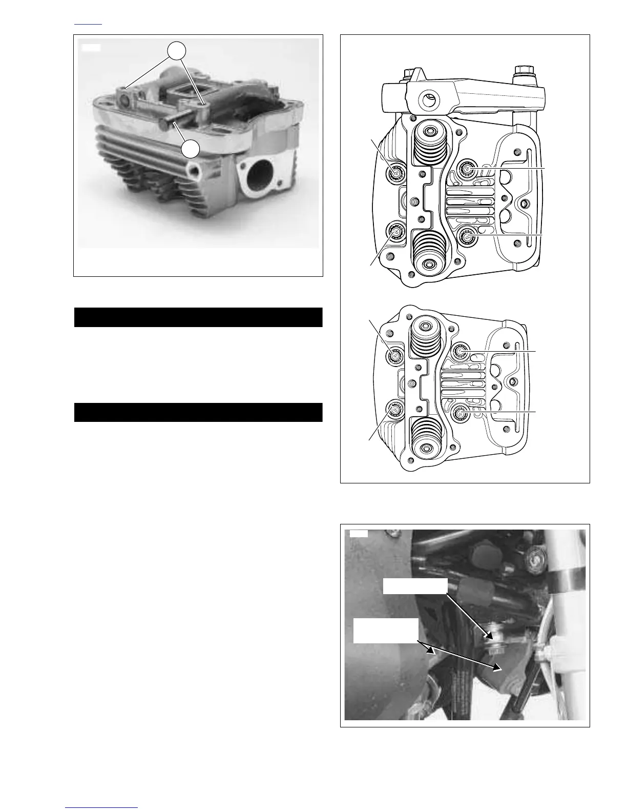
Figure 3-7. Removing Rocker Arm Shafts
5698
2
1. Position of Rocker Arm Retaining Bolts
2. Retaining Notch
1
Figure 3-8. Head Screw Loosening/Tightening Sequence
Figure 3-9. Front Isolator Mount and Tie Bar
 Loading...


