3-14 2002 Buell X1: Engine
HOME
DISASSEMBLY
NOTE
Disassembly of front cylinder exhaust valve components
requires front isolator mount removal.
1. See Figure 3-11. Compress valve springs with VALVE
SPRING COMPRESSOR (Part No. HD-34736B).
2. See
Figure 3-10. Remove valve keepers (7), upper collar
(8) and valve springs (5, 6). Mark valve keepers for reas-
sembly in their original locations.
3. Use a fine tooth file to remove any burrs on the valve
stem at the keeper groove.
4. Mark valve to ensure that it will be reassembled in the
same head. Remove valve (10), valve stem seal (11) and
lower collar (9).
5. Repeat the above procedure for the other valve.
6. Disassemble the other head using the same procedure.
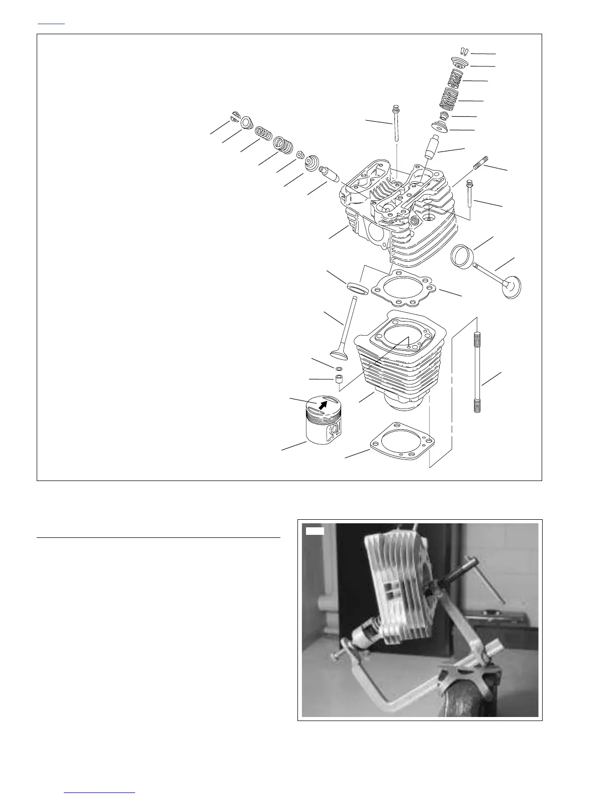
Figure 3-10. Cylinder Head, Cylinder and Piston
18
7
8
5
6
11
9
16
17
10
14
2
10
12
4
13
19
3
15
17
8
5
7
1
16
5
6
11
9
20
1. Head Screw, Long (2)
2. Head Screw, Short (2)
3. Arrow, Piston Direction
4. Head Gasket
5. Inner Valve Spring (2)
6. Outer Valve Spring (2)
7. Valve Keeper (4)
8. Upper Collar (2)
9. Lower Collar (2)
10. Valve (1 Intake, 1 Exhaust)
11. Valve Stem Seal (2)
12. Cylinder Stud (4)
13. Base Gasket
14. O-Ring (2)
15. Insert/Dowel (2)
16. Valve Guide (2)
17. Valve Seat (2)
18. Cylinder Head
19. Cylinder
20. Piston
xlhcylhead
Figure 3-11. Valve Spring Compressor
(Part No. HD-34736B)
5694
 Loading...


