4-30 2002 Buell X1: Fuel System
HOME
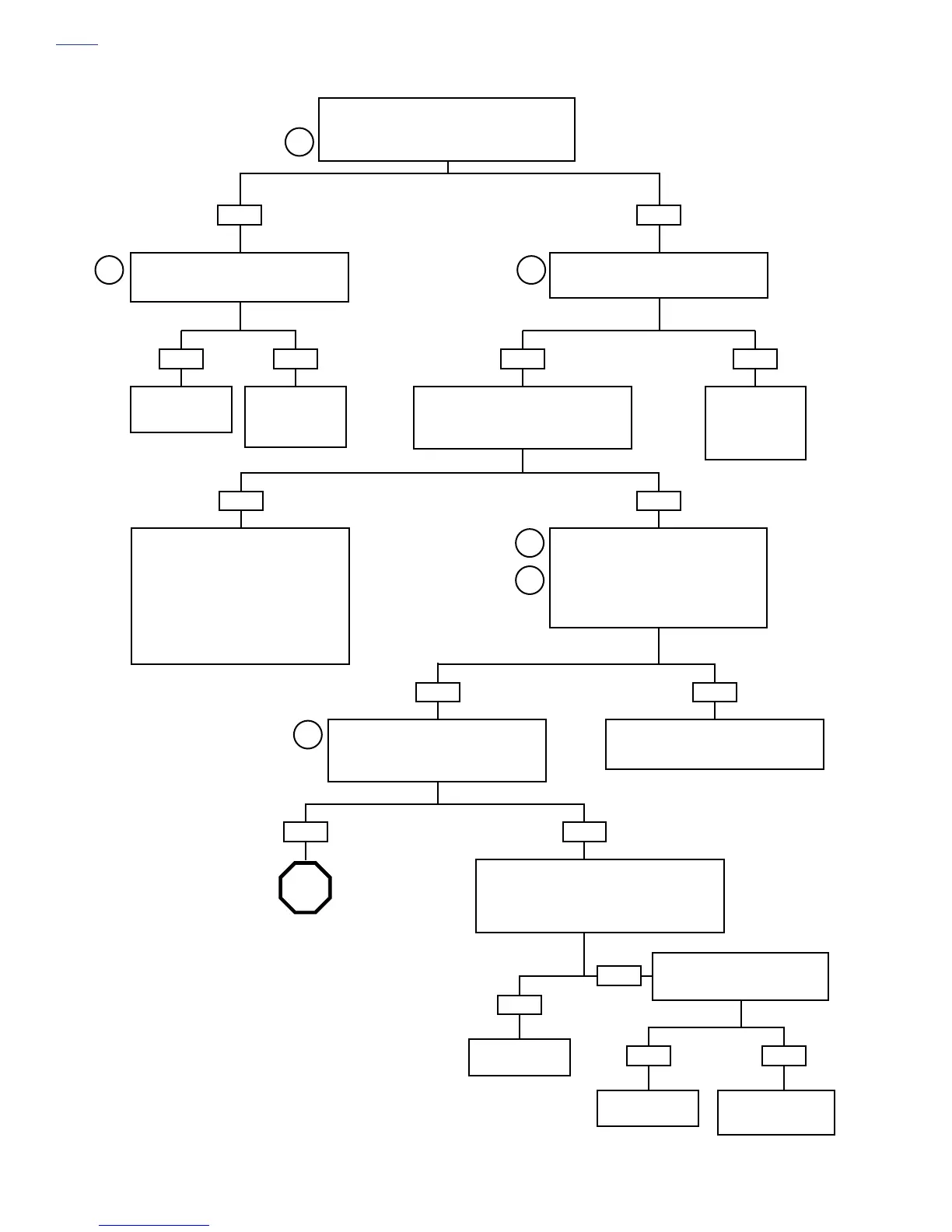
Test 4.12 (Part 2 of 3)
Continued from Test 4.12 (Part 1 of 3).
Check spark plug condition. Replace if fouled. Check
spark at both plugs while cranking. Spark present?
YES NO
2
Check for battery voltage at Terminal B of
coil connector [83] using DVOM. Power
present after key ON?
Disconnect fuel injector connector and
attach Fuel Injector Test Lamp (HD-34730-
2C). Crank engine. Does lamp flash?
Check engine
compression. See
3.2 ENGINE.
YES
Correct problems
found under
4.22
TROUBLE CODES
23 AND 32
.
NO
Disconnect coil connector [83]. Gently con-
nect test lamp to connector [83] Terminal A
(front cylinder) or Terminal C (rear cylinder).
Crank engine. Does light flash?
YES
Open in GY wire
between splice for
fuel pump wire and
ignition coil. Repair
open.
NO
Faulty coil connection, spark plug wires
or coil. Proceed as follows:
• Check coil connection.
• Test spark plug cable resistance. See
4.16
MISFIRE.
• Check coil by substituting one known to be
good.
OR
Check coil resistance. See
4.31 IGNITION
COIL
.
YES
Connect Breakout Box. Check continuity
between ignition coil Terminal A of connec-
tor [83] and Breakout Box (BK) Pin 7.
Measure resistance between ignition coil
Terminal C and ECM Pin 6 [10B].
Resistance should be less than 1.0 ohm.
Is it?
NO
Disconnect cam position sensor connector
[14]. With ignition ON, measure voltage
between Terminal A (+) and Terminal C (-)
of connector [14B]. Is 5 volts present?
YES
Poor connection at connector [10B], [83] or
open in harness between coil and
ECM. Repair open.
NO
With ignition OFF, measure resistance between
connector [14] Terminal A and Breakout Box (GY)
Pin 1. Also between connector [14] Terminal C
(BK/W wire) and ECM Pin 8 on connector [11B]. Is
resistance greater than 1.0 ohm?
NO
Go to Test 4.12
(Part 3 of 3).
YES
YES
Repair open
circuit.
NO
Check for continuity between Ter-
minal A connector [14B] and
ground. Continuity present?
YES
Repair short
to ground.
NO
3 4
5
6
7
STOP
Replace ECM. See
4.29 ELECTRONIC
CONTROL MODULE
.
7210
7205
7215
7220
7225
7240
7241
7250