4-70 2002 Buell X1: Fuel System
HOME
TROUBLE CODES 24 AND 25 4.23
GENERAL
Front Ignition Coil (Code 24)
And Rear Ignition Coil (Code 25)
A Code 24 or 25 will set if the ignition coil rise time is out of
range. This could occur if there is an open coil or loss of
power to the coil. If both codes are set, it is likely a coil power
failure or a coil failure.
See
Figure 4-54. The coil receives power from the ignition
relay at coil pin B (4) at the same time that the fuel pump and
injectors are activated. The fuel pump is active for the first two
seconds after the ignition switch is turned ON and then shuts
off until RPM is detected from the cam position sensors, at
which time it is reactivated.
DIAGNOSTICS
Diagnostic Notes
The reference numbers below correlate with the circled num-
bers on the Code 24/25 flow charts.
1. Use HARNESS CONNECTOR TEST KIT (Part No. HD-
41404), purple pin probes and patch cord.
2. Connect BREAKOUT BOX (Part No. HD-42682) to ECM.
See
4.7 BREAKOUT BOX.
Scanalyzer Notes
The Scanalyzer icon appears at those points in the flow chart
where the Scanalyzer can be used. If a number is printed
next to the icon, then refer to the Scanalyzer notes at the bot-
tom of the flow chart.
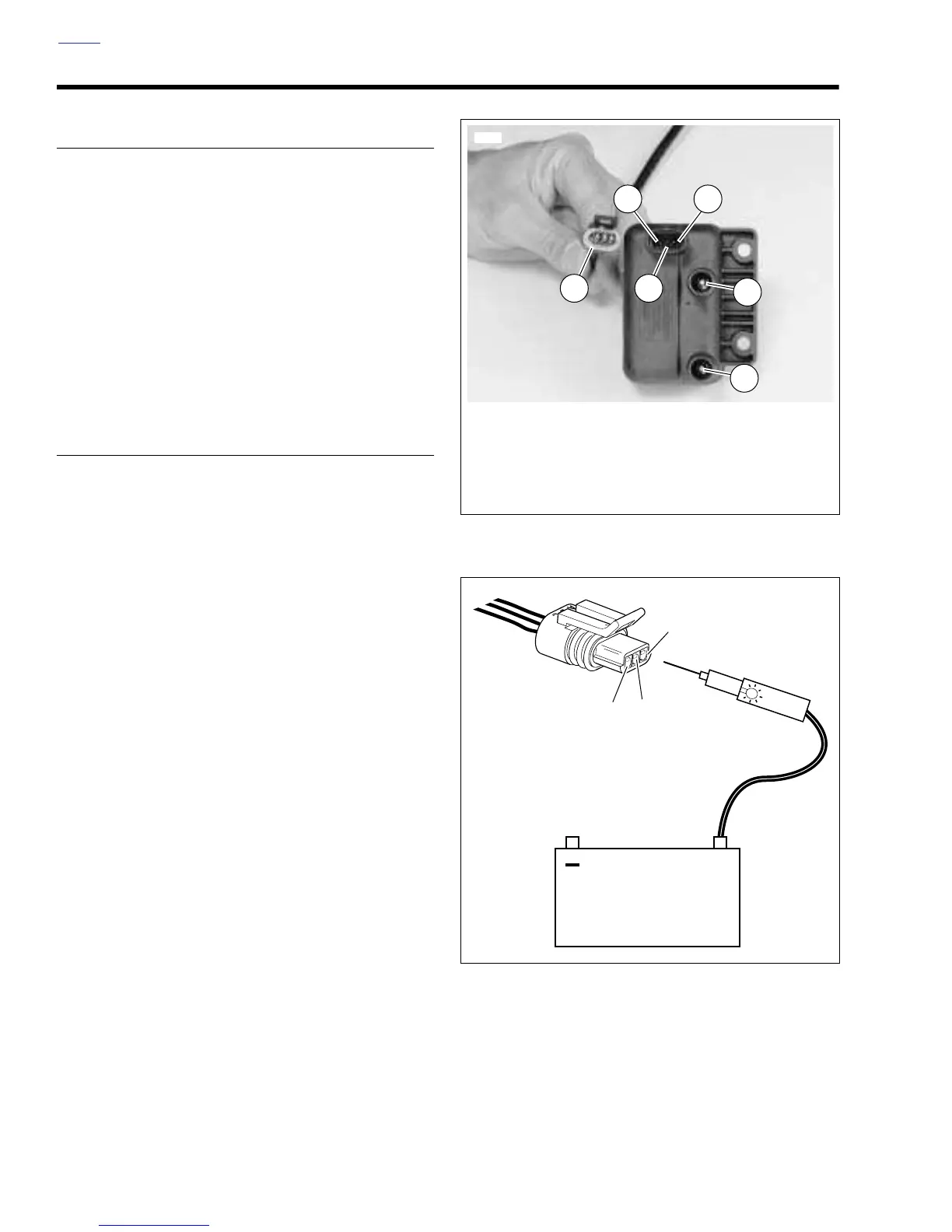
Figure 4-54. Ignition Coil
Figure 4-55. Testing Ignition Coil Connectors
1
6766
2
35
4
1. Rear Cylinder Spark Plug Cable
2. Front Cylinder Spark Plug Cable
3. Coil Pin A (Rear Cylinder)
4. Coil Pin B (12 VDC)
5. Coil Pin C (Front Cylinder)
6. Coil Connector [83]
6
+
b0638x4x
A
B
C
Battery
 Loading...


