2002 Buell X1: Electrical 7-13
HOME
TESTING/REPLACEMENT
Side Stand Switch
See
Figure 7-9. The side stand switch is a simple spring
loaded plunger. The switch completes a path to ground for
the ignition relay when the side stand is in the retracted posi-
tion. Test the switch as follows:
1. Unplug the 2-place side stand switch connector [60].
2. Test the switch using an ohmmeter.
a. With side stand down (1) (switch open), the switch
should show ∞ ohms (infinite ohms).
b. With side stand up (2) (switch closed), the switch
should show 0 ohms or little resistance.
3. Replace the assembly with a new switch if necessary.
Remove side stand switch from frame by removing two
nuts.
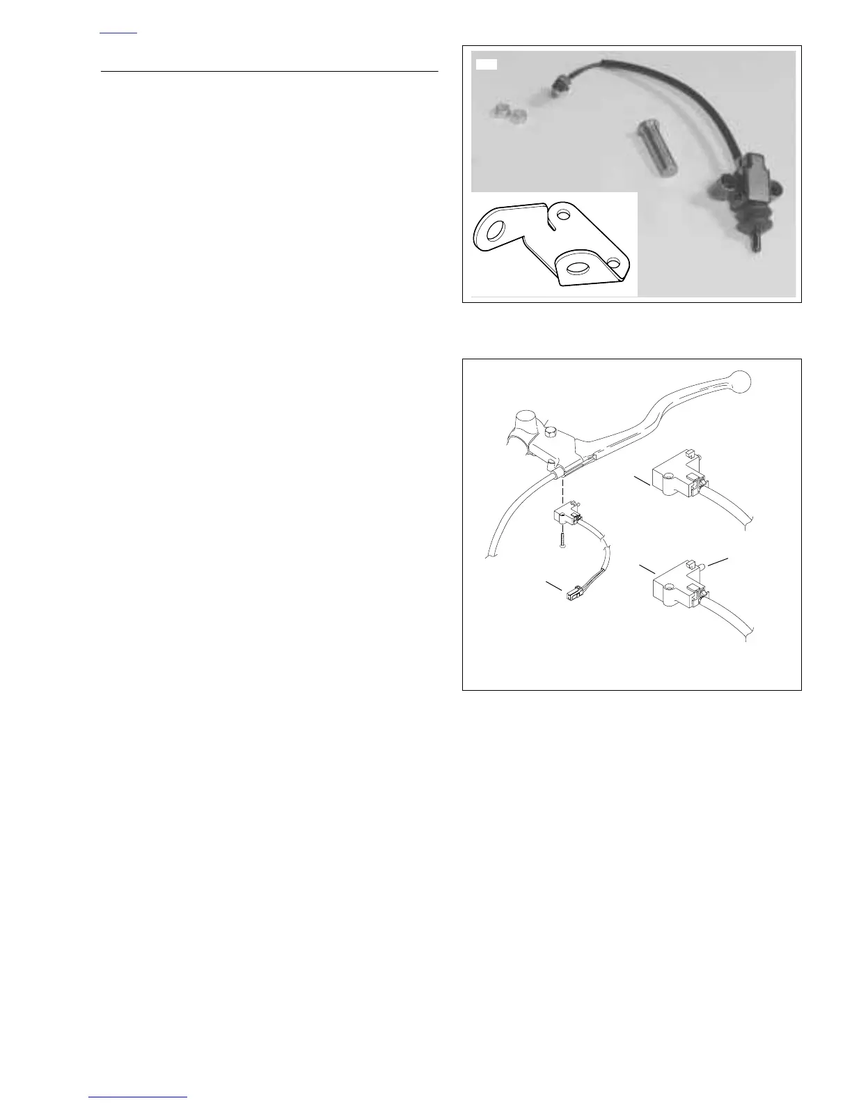
Clutch Switch
See
Figure 7-10. The clutch switch attaches to the clutch con-
trol lever bracket. The switch completes a path to ground for
the ignition relay and the starter relay when the clutch is dis-
engaged. Test the switch as follows:
1. Unplug the 2-place clutch switch connector [95].
2. Test the switch using an ohmmeter.
a. With clutch engaged (1) (switch open), the switch
should show ∞ ohms (infinite ohms).
b. With clutch disengaged (2) (switch closed), the
switch should show 0 ohms or little resistance.
3. Replace the assembly with a new switch if necessary.
a. Remove small Phillips screw.
b. Depress clutch lever and hold.
c. Detach switch by depressing switch trigger button
and pulling switch towards the end of the handlebar.
d. Install new switch.
Figure 7-9. Side Stand Switch and Bracket
Figure 7-10. Clutch Switch