7-14 2002 Buell X1: Electrical
HOME
Ignition Relay
See
Figure 7-11. The ignition relay is under the seat. Test the
relay as follows:
1. See
Figure 7-12. Remove seat and locate ignition relay
(1) within relay/diode block.
2. Test the relay in the same fashion as the starter relay.
See Section 5.
3. Replace the relay with a new relay if necessary.
Starter Relay
The starter relay (2) is under the seat. See
5.3 STARTING
SYSTEM DIAGNOSIS
.
Ignition Fuse
See
Figure 7-11. The ignition fuse (3) is in the fuse block
under the seat. Always replace the fuse with another 20
ampere fuse.
Diodes
1. Remove seat and locate diodes within relay block (2).
2. Test diodes using Starter Test flow charts under
DIAG-
NOSTICS.
3. Identify the diode which must be replaced. Replace both
diodes if necessary.
4. Replace the diodes by pulling them straight out. The
spare diode may be used in either circuit as long as it is
installed in the correct direction.
Main Circuit Breaker
Attached to the frame above the battery, the main circuit
breaker links the ignition key switch and the battery. See
7.23
FUSES AND CIRCUIT BREAKERS for more information.
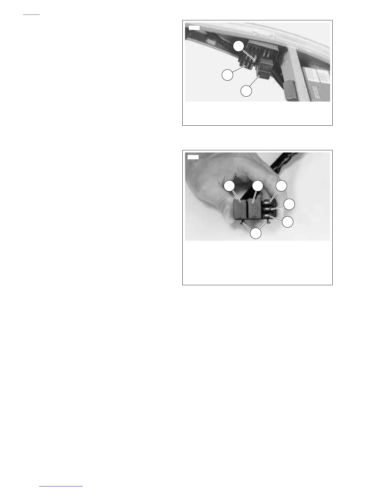
Figure 7-11. Fuse and Relay Blocks
Figure 7-12. Ignition Relay and Diodes
1
6982
1. Fuse Block
2. Relay Block
3. Ignition Fuse
2
3
1. Ignition Relay
2. Starter Relay
3. Starter Circuit Diode
4. Ignition Circuit Diode
5. Spare Diode
6. Mounting Tabs
6763
3
4
6
5
21