107
Operating and functions
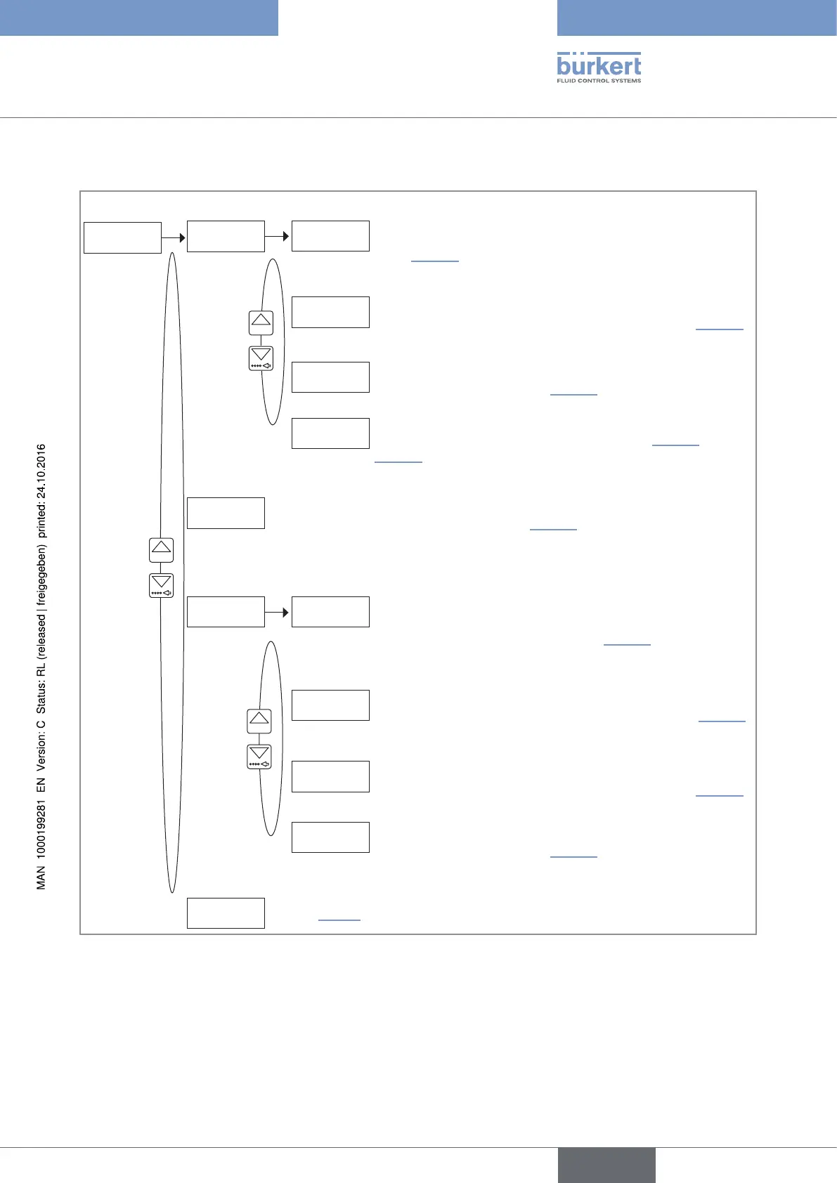
10.7.18 Configuring the outputs (general diagram)
OUtPUt
0......9
DO1
PULSE
ALARM
WARNiNG
DO2
DO3
Configuring the transistor output DO1 to send a pulse when a
dosing is finished. See chap. 10.7.21.
Configuring the transistor output DO1 to switch when an
alarm is generated during or at the end of a dosing. See
chap. 10.7.19.
0......9
END DOSE
Configuring the transistor output DO1 to switch when a
warning message is emitted by the device. See chap. 10.7.20.
Configuring the transistor output DO1 as a pulse output
proportional to a volume or a mass. See chap. 10.7.22 and
10.7.23.
DO4
The output DO2 is dedicated to the control of the main valve (installed into
the pipe with high flow rate). See chap. 10.7.24.
VALVE
ALARM
WARNiNG
Configuring the transistor output DO3 to send a pulse when a
dosing is finished. See chap. 10.7.21.
Configuring the relay output DO3 to control an auxiliary
valve (installed on a low flow pipe). This configuration is
automatically set if the relay output DO2 is parametered with a
filling percentage < 100%. See chap. 10.7.25.
Configuring the relay output DO3 to switch when an alarm is
generated during or at the end of a dosing. See chap. 10.7.19.
END DOSE
Configuring the transistor output DO3 to switch when a
warning message is emitted by the device. See chap. 10.7.20.
See Fig. 79.
0......9
Fig. 78 : Diagram 1/2 of the "OUTPUT" parameter of the Parameters menu
English
Type 8025 - 8035 - SE35 BATCH