21
Technical data
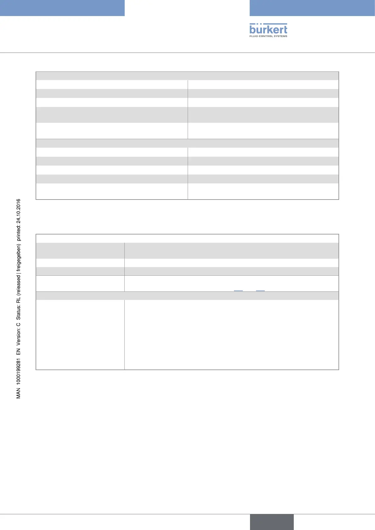
Relay output DO2 and DO3
• operating • hysteresis, adjustable thresholds, normally open
• DO2 function • valve 100%, cannot be modified
• DO3 function • alarm (can be configured and parametered)
• electrical data of the load
(non UL recognized devices)
• 230 V AC / 3 A or
40 V DC / 3 A (resistive load)
• electrical data of the load
(UL recognized devices)
• max. 30 V AC and 42 V peak / 3 A or
max. 60 V DC / 1 A
Digital inputs DI1 to DI4
• commutation threshold V
on
• 5...36 V DC
• commutation threshold V
off
max. • 2 V DC
• min. pulse duration • 100 ms
• input impedance • 9,4 kW
• protection • galvanically isolated, and protected against polarity
reversals and voltage spikes
6.2.6 Specifications of a remote flow sensor connected to a
8025 Batch in panel version
Signal from the remote sensor
• type • pulse, sine-wave (typical sensitivity 50 mV peak-to-peak at 250 Hz),
"on/off", or standard voltage 0...5 V DC
• frequency • 0,6...2200 Hz, can be parametered
• max. voltage • 36 V DC
Input impedance
depends on the position of selector "LOAD" on the electronic board of the
8025 Batch in panel version. See chap. 8.7 and 8.9.
Power supply
• dosing controller supplied
with a 12...36 V DC voltage
supplied by the dosing controller depending on the position of selector
"SENSOR SUPPLY" of the 8025 Batch in panel version, either:
• 5 V DC, 30 mA max.
• (L+) – 12V: supply voltage (L+) of the dosing controller minus 12 V DC
(minus 12,5 V DC max.), 80 mA max.
• L+: supply voltage (L+) of the dosing controller (minus 1,5 V DC max.),
140 mA max.
English
Type 8025 - 8035 - SE35 BATCH