13
Description
5 DESCRIPTION
5.1 Area of application
When mounted in series with one or two valves the device enables the dosing of one or several quantities of a
liquid.
It controls the opening or closing of the valves via the relay outputs and counts the quantity of flown liquid.
The dosing is done either locally by pressing the navigation keys under the display or remotely by a PLC via one
up to four digital inputs.
The dosing principle is described in chap. 10.5.
The eight available dosing modes are described in chap. 10.6.
5.2 Construction of the device
The device has:
• four digital inputs (called DI1 to DI4),
• two transistor outputs (called DO1 and DO4, which can be parametered),
• two relay outputs (called DO2 and DO3, which can be parametered) and
• four totalizers (two volume or mass totalizers and two totalizers of the done dosings).
Depending on the version the device is energized by a 12...36 V DC or a 115/230 V AC power supply.
Electrical connection is made on the terminal blocks of the electronic board, either directly or via 2 or 5 cable glands.
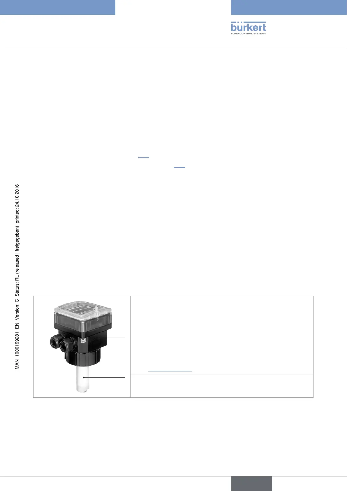
5.2.1 Construction of the 8025 Batch in compact version
A
B
A : Paddle-wheel flow sensor, the rotation of which generates pulses.
Set in rotation by the flow, the 4 permanent magnets integrated in
the vanes of the paddle generate pulses, the frequency of which is
proportional to the flow velocity of the fluid. A conversion coefficient
specific to each pipe (material and diameter) is necessary to establish
the flow rate value associated with the measurement.
The conversion coefficient (K-factor) expressed in pulses per litre is
given in the Operating Instructions for the S020 fitting used, available
under www.burkert.com
B : Dosing controller with display and 2 cable glands
Fig. 1 : Construction of the 8025 Batch in compact version
English
Type 8025 - 8035 - SE35 BATCH