54
Electrical installation and Wiring
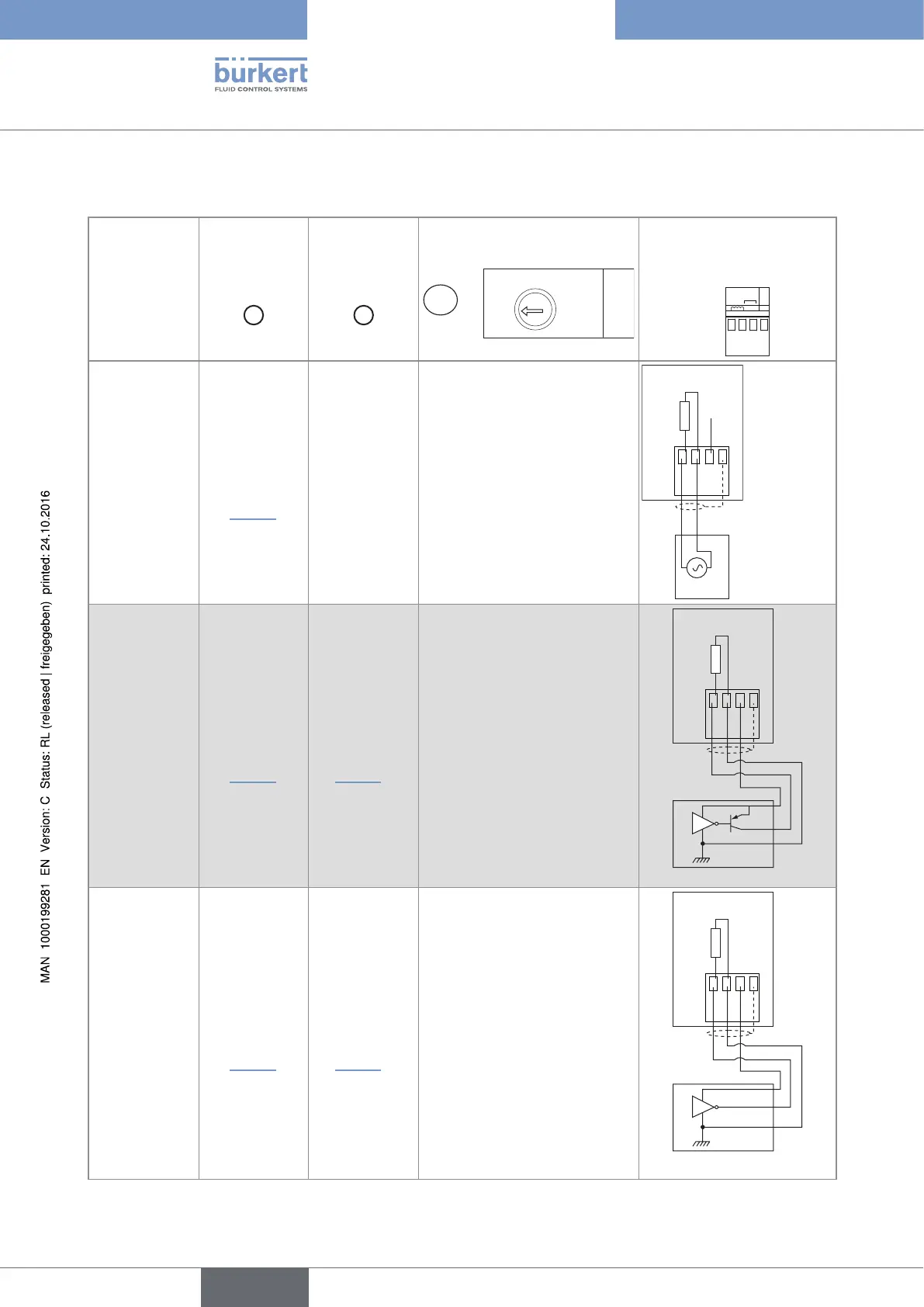
Tab. 3 : Position of selectors "SENSOR TYPE" and "LOAD" of the 8025 Batch in panel or in wall-mounted version, and
terminal assignment of terminal block "FLOW SENSOR" depending on the signal emitted by the remote flow sensor
Type of signal
emitted by the
remote flow
sensor
Selector
"SENSOR
TYPE"
C
Selector
"SENSOR
SUPPLY"
A
Selector "LOAD"
B
LOAD
39K
2.2K
Terminal assignment of
terminal block "FLOW
SENSOR"
FLOW
R
SUPPLY
NC
PULSE
INPUT
2
+-
sine-wave
(coil)
→ Set the
selector
on "COIL"
(Fig. 33)
→ Any
position.
→ Set selector "LOAD" on
"39K": the input impedance
on terminals 1 and 2 of
terminal block "FLOW
SENSOR" will then be
39 kW
213PE
NC
39 kΩ
8025
Flow sensor
pulse, PNP
→ Set the
selector on
"NPN/PNP"
(Fig. 33)
→ Set the
selector as
shown in
Fig. 34.
→ Set selector "LOAD" on
"39K": the input impedance
on terminals 1 and 2 of
terminal block "FLOW
SENSOR" will then be
39 kW
213PE
39 kΩ
8025
Flow sensor
0-5 V DC
standard
voltage signal
(TTL, for
example)
→ Set the
selector on
"NPN/PNP"
(Fig. 33)
→ Set the
selector as
shown in
Fig. 34.
→ Set selector "LOAD" on
"39K": the input impedance
on terminals 1 and 2 of
terminal block "FLOW
SENSOR" will then be
39 kW
213PE
39 kΩ
8025
Flow sensor
English
Type 8025 - 8035 - SE35 BATCH