26
Installation and commissioning
5,5
11,5
20
5
→ Strip 20 mm of the cable.
→ Cut the central wire (earth) so that its length is equal to 11.5 mm.
→ Expose 5.5 mm of the wires on the stripped cable.
→ Insert each wire into the appropriate pin on the terminal block [5] (see chap. 8.3.3
and 8.3.4).
→ Tighten the terminal block [5] wired to the body [4].
→ Tighten the connector nut [1].
Fig. 18 M12 multi-pin connector (not provided)
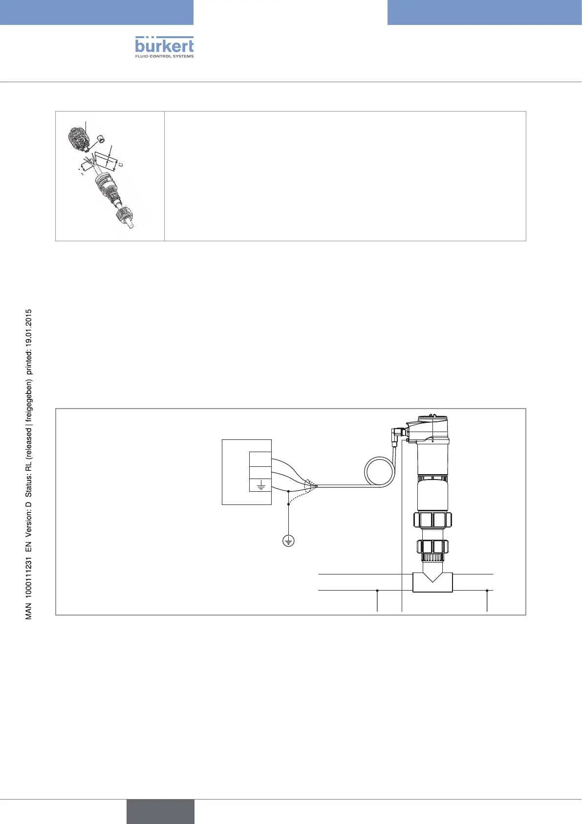
8.3.2. Equipotentiality of the installation
To ensure the equipotentiality of the installation (power supply - device - medium):
→ Connect together the various earth spots in the installation to eliminate the potential differences that may
occur between different earthes.
→ Observe faultless grounding of the shield of the power supply cable.
→ Special attention has to be paid if the device is installed on plastic pipes because there is no direct earthing
possible. Proper earthing is performed by earthing together the metallic devices such as pumps or valves, that
are as close as possible to the device.
Power supply
12-36 V DC
+
-
Fig. 19 Equipotentiality skeleton diagram with pipes in metal
English
Type 8202 ELEMENT