46
Operating and functions
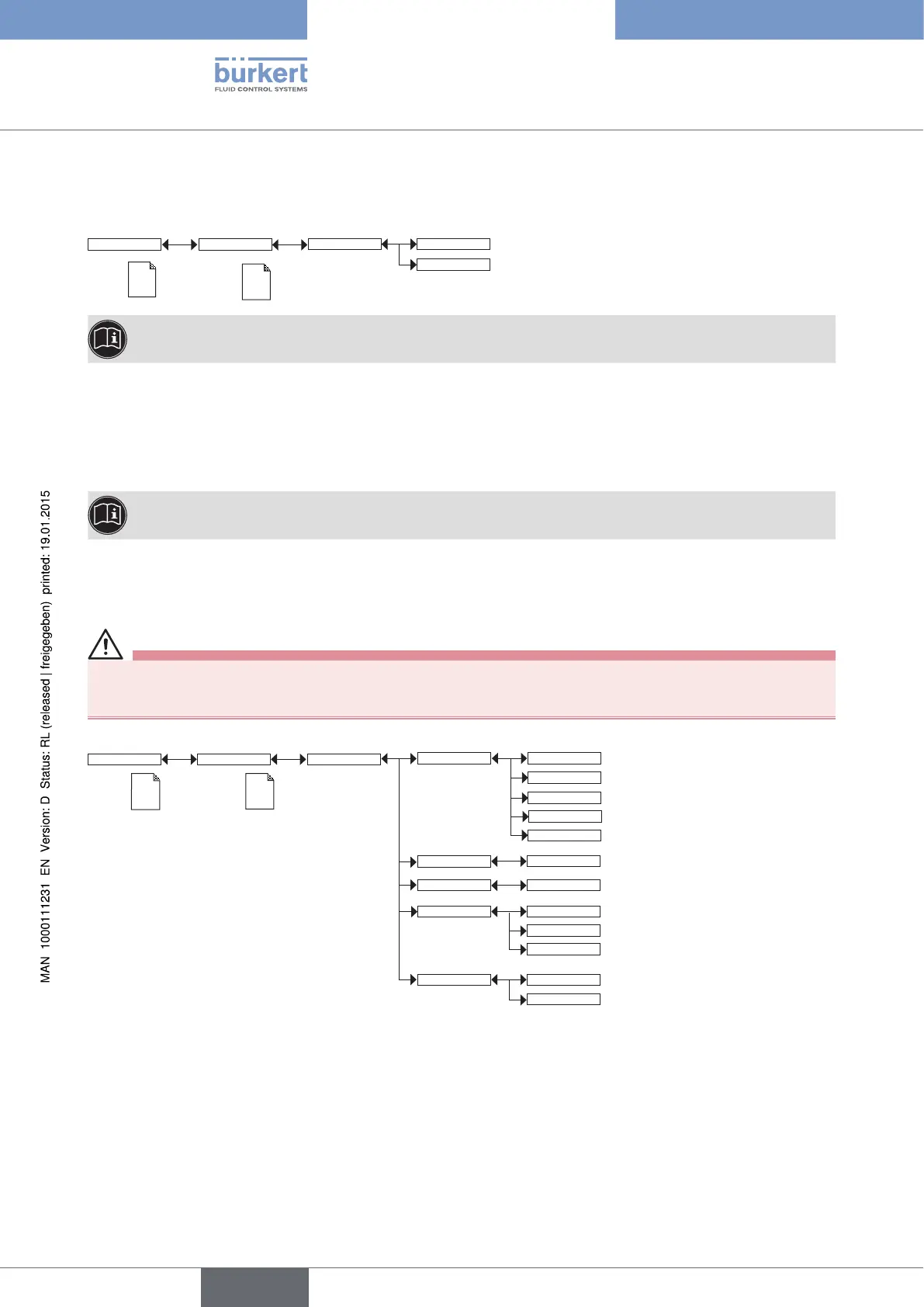
9.11.8. Choosing the output wiring mode
See chap. 9.9 to access the Parameters menu.
Param
This is
when the
device is be-
ing parame-
tered............
....................
This is
when the
device is be-
ing parame-
tered............
....................
Outputs
HWMode
sink/NPN
source/PNP
The setting has no effect on a version with one fixed connector, if the sole current output is wired. See
Fig. 23.
The wiring mode is the same for all outputs.
If you choose "sink NPN", the current outputs must be wired in sinking mode and the transistor outputs in NPN
mode.8.3
If you choose "source PNP", the current outputs must be wired in sourcing mode and the transistor outputs in
PNP mode.
See the wiring for the outputs in chap. 8.3.
9.11.9. Setting the parameters of the current outputs
See chap. 9.9 to access the Parameters menu.
WARNING
Risk of injury due to wrong adjustment.
• Before setting the parameters for the outputs, choose the type of probe (see chap. 9.11.11) mounted on the
transmitter.
The 2nd current output "AC2" is only available on a version with 2 fixed connectors.
This is
when the
device is be-
ing parame-
tered............
....................
Param
This is
when the
device is be-
ing parame-
tered............
....................
AC1/AC2
PVar:
4mA:
INPUT
20mA:
INPUT
DiagnosMode: None
22mA
Filter:
Fast
None
Slow
pH
TempC
mV_pH
mV_ORP
TempF
Outputs
PVAR: choose a process value associated with current output 1 or current output 2 respectively. The possible
choices depend on the selected sensor type, whether pH or ORP.
4mA: choose the value of the process value (previously selected), associated with a current of 4 mA, for each
current output.
20mA: choose the value of the process value (previously selected), associated with a current of 20 mA, for each
current output.
Functions "4mA" and "20mA" are used to define the measurement range for the process value associated with
the current on the 4-20 mA output.
English
Type 8202 ELEMENT