28
Installation and commissioning
14-36 V DC
+ -
1
2
3
4
Load 1 (solenoid valve for instance)
Load 2
(solenoid valve for instance)
Power supply
white
blue
black
brown
grey
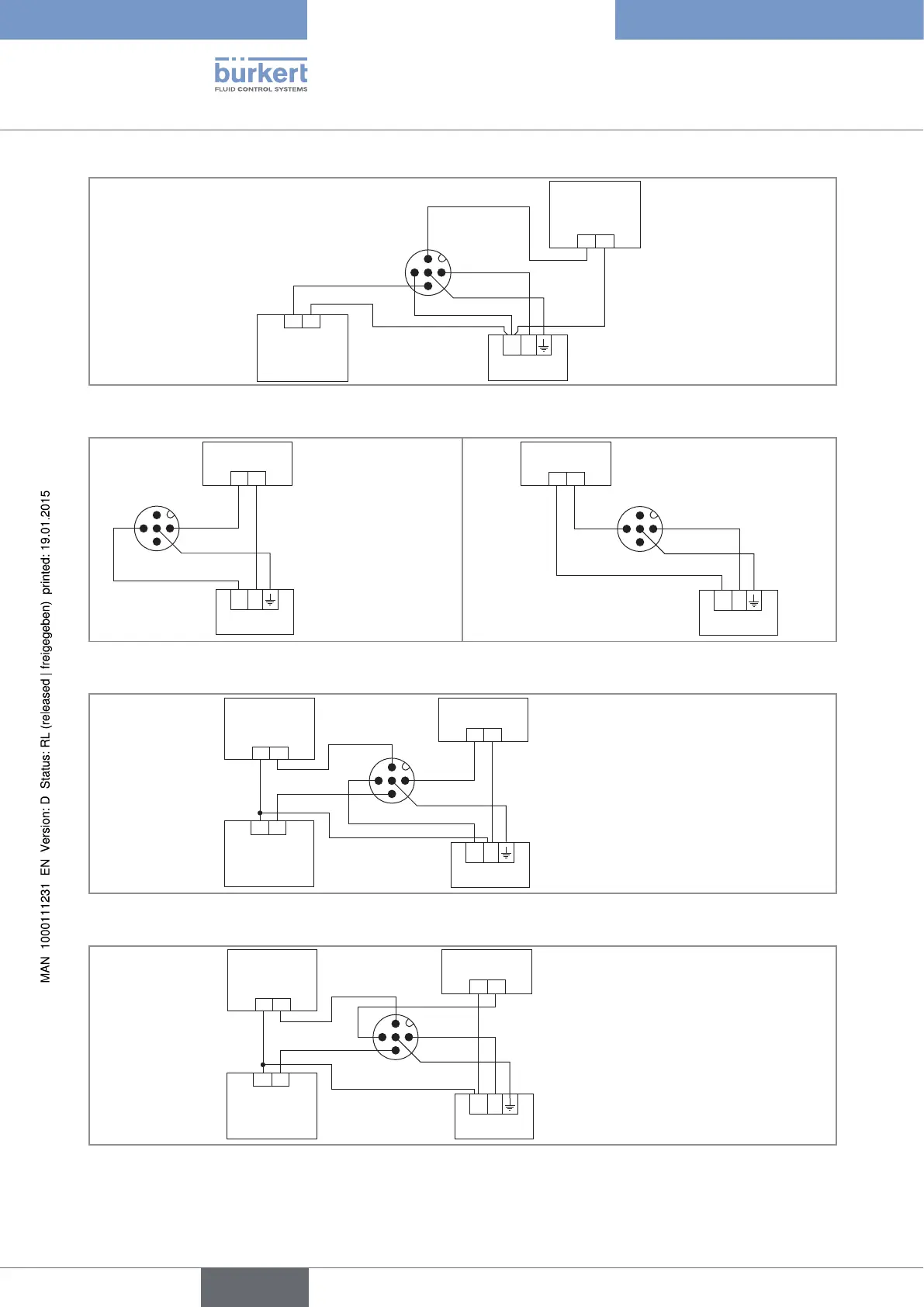
Fig. 22 PNP wiring of both transistor outputs (software setting "PNP/source", see chap. 9.11.8), of a version with 1 M12
fixed connector
14-36 V DC
+ -
+ -
1
2
3
4
Power supply
4-20mA input at external
device
brown
blue
grey
14-36 V DC
+ -
+ -
1
2
3
4
Power supply
4-20mA input at external
device
brown
blue
grey
Fig. 23 Possible wirings of the current output (whatever the software setting, "NPN/sink" or "PNP/source", see
chap. 9.11.8), of a version with 1 M12 fixed connector
14-36 V DC
+ -
+ -
1
2
3
4
Load 2
Load 1
4-20mA input at external device
brown
grey
blue
white
black
Power supply
Fig. 24 NPN wiring of both transistor outputs and wiring the current output in sinking mode (software setting "NPN/sink",
see chap. 9.11.8), of a version with 1 M12 fixed connector
14-36 V DC
+ -
+ -
1
2
3
4
Load 2
Load 1
4-20mA input at external device
brown
grey
blue
white
black
Power supply
Fig. 25 PNP wiring of both transistor outputs and wiring the current output in sourcing mode (software setting " PNP/
source", see chap. 9.11.8), of a version with 1 M12 fixed connector
English
Type 8202 ELEMENT