22
Mechanical installation
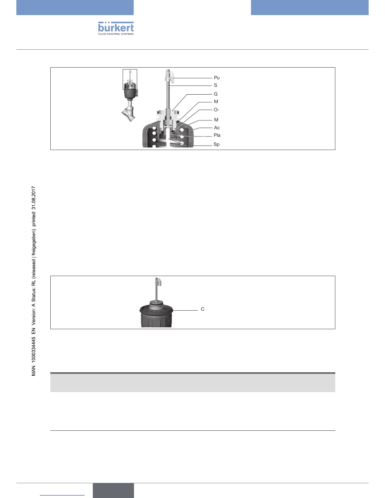
Guide element
O-ring
Plastic part
Puck
Switch spindle
Spindle (actuator)
Max. 8 Nm
Actuator cover
Max. 1 Nm
Figure 13: Installing the switch spindle (2), external pilot air duct
→ Press O-ring down into the actuator cover.
→ Manually screw the switch spindle (and the slipped over guide element) to the spindle of the actuator
with the plastic part and do not tighten initially.
→ Screw the guide element into the cover of the actuator with a face pin wrench* (tightening torque: max.
8Nm).
→ Tighten the switch spindle on the spindle of the actuator. A slot is provided on the top side (tightening
torque:max.1Nm).
→ Push puck onto the switch spindle and lock into position.
2. Installing the device
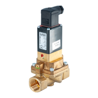
Cover ring
Figure 14: Attaching cover ring
→ Wind cover ring onto actuator cover (only for actuator size ø50 and ø63).
NOTE
DamageorfunctionaloutageofthePCB
▶ Ensurethatthepuckliesatintheguiderail.
→ Alignthepuckandthedevicesothatthepuckrestsintheguiderailofthedevice(seefollowinggure).
* journal Ø: 3 mm; journal gap: 23.5 mm