23
Mechanical installation
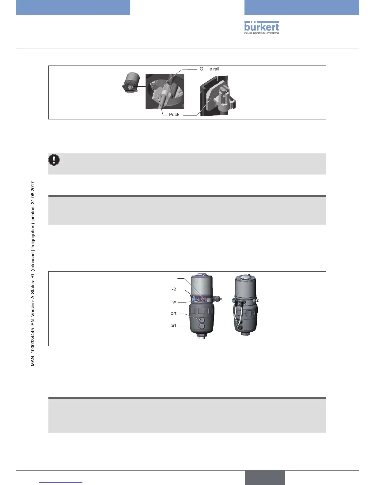
Guide rail
Puck
Figure 15: Aligning the puck
→ Press the device all the way down to the actuator and turn it into the required position.
Ensure that the pneumatic connections of the device and those of the valve actuator are situated
preferablyverticallyoneabovetheother(seeFig.below).Fordierentpositioning,longerhosesmay
be required than those supplied in the attachment kit.
NOTE
Damageormalfunctionduetoingressofdirtormoisture.
To observe the degree of protection IP65 or IP67:
▶ Tighten fastening screws only with a tightening torque of max. 1.5 Nm.
→ Attach device to the actuator using the two side fastening screws. In doing so, tighten the screws only
hand-tight (max. torque: 1.5 Nm).
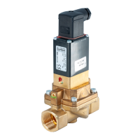
3. Pneumatically connecting device and actuator
Pilot air outlet 2-1
Pilot air outlet 2-2
Upper pilot air port
Lower pilot air port
Example ∅80, CFA
Fastening screw
Figure 16: Pneumatically connecting device and actuator
→ Screw plug-in hose connector onto device and actuator.
→ Using the hoses supplied in the attachment kit, make the pneumatic connection between the device and
actuator with the following table.
NOTE
Damageormalfunctionduetoingressofdirtormoisture.
To observe the degree of protection IP65 or IP67:
▶ Only for CFA and CFB: Connect the pilot air outlet which is not required to the free pilot air port of the
actuator or seal with a plug.