62-11640 5–16
Table 5–1 Configuration Settings
(Refer to Section 5.2.3 for instructions on entering Configuration settings)
Configuration Selections Description
CONFIGURATION SETTINGS
UNIT IDENTIFICATION
UNIT MODEL NUMBER # A list of configurable
model numbers
Indicates to the main microprocessor the model num-
ber of the unit. There are several model numbers
provided in the list. Select the model number printed
on the Model/Serial Number nameplate.
NOTE
The unit model number selection may have an asterisk (*) in the place of the 7th character. If that is the
case, then that number may be selected as long as all of the other numbers and letters match exactly.
TRAILER ID # A customer assigned ID # may be entered. This may
be up to 10 characters long. Numbers, letters, and
spaces may be entered by scrolling through the
available list. Refer to Section 5.2.3 for instructions
on entering the Trailer ID.
NOTE
The default display for this Configuration is “TRAILER ID #”. The display may be modified if the “UNIT
OPERATION’” Configuration in the Rail Settings group is set to “RAIL”. If this Configuration is set to
“RAIL” then “ASSET ID #” or “CAR ID #” may display rather than the “TRAILER ID #” default. Refer to
the UNIT OPERATION Configuration later in this table.
UNIT SERIAL NUMBER # The unit S/N may be entered. Numbers, letters, and
a space are available by scrolling through the avail-
able list. Refer to Section 5.2.3 for instructions on
entering the unit serial number.
SET NEW HOURS This Configuration will display when a replacement main microprocessor is in-
stalled. It allows entry of the hours (from the existing microprocessor) into the
replacement microprocessor. This Configuration will only display until one of
the hour meters reaches 25 hours. Changes to these values may be made for
up to 60 minutes.
SET DATE AND TIME Indicates to the main microprocessor the current date and time. Refer to Sec-
tion 5.2.3 for instructions on entering the date and time.
NOTE
Date and Time may also be configured under “Other Settings”.
BACK
EXIT
UNIT IDENTIFICATION
SETPOINT(S) & RANGE LOCK
START-STOP SETTINGS
INTELLISET & PRODUCTSHIELD
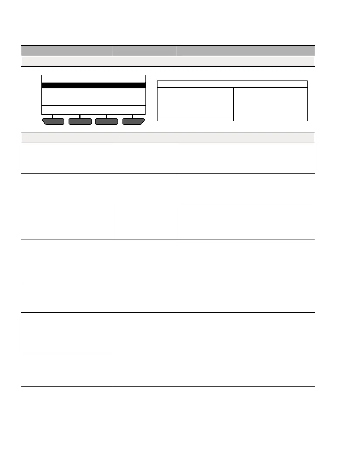
CONFIGURATION SETTINGS (1 OF 11)
UNIT IDENTIFICATION
SETPOINT(S) & RANGE LOCK
START-STOP SETTINGS
INTELLISET & PRODUCT SHIELD
ENGINE SETTINGS
ALARM SETTINGS
HOUR METERS
REMOTE SENSORS
OTHER SETTINGS
RAIL SETTINGS
AUTO FRESH AIR SETTINGS
PRESS UP/DOWN TO DISPLAY AVAILABLE CONFIGURATIONS
AVAILABLE CONFIGURATIONS INCLUDE

 Loading...

