62-11640 8–4
8.4 EXTERNAL SURFACE SERVICE
Procedures for servicing or maintaining the automatic
fresh air exchange, grille, surround, doors, door latches
and display module are provided in the following sub-
paragraphs.
8.4.1 AutoFresh Fresh Air Exchange
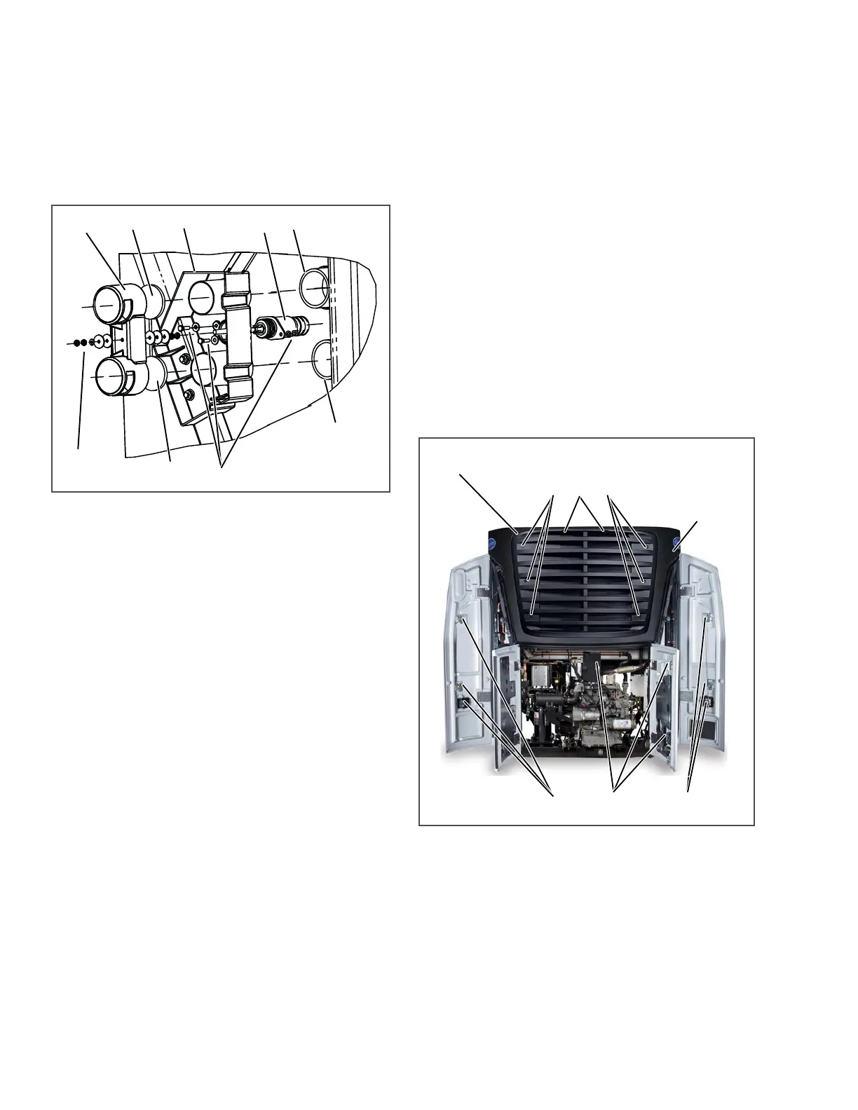
Figure 8.1 Automatic Fresh Air Exchange
1. Cover
2. Gasket
3. Housing
4. Solenoid
5. Inlet Connection
6. Outlet Connection
7. Solenoid Hardware
8. Cover Hardware
To replace the cover and/or cover gaskets and sole-
noid, do the following.
a. Cover And/Or Cover Gaskets
1. Ensure the unit will not start automatically by
disabling any two way communication and plac-
ing the STOP/RUN-OFF switch in the OFF posi-
tion. Disconnect the high voltage source and
lockout/tagout the receptacle.
2. Loosen outermost cover mounting nut (8, Fig-
ure 8.1) to unlock hardware and remove hard-
ware holding cover (1) in place.
3. Slide cover off solenoid shaft (4), remove and
replace gaskets (2). Slide cover in place against
inner hardware to ensure cover gasket is slightly
compressed to form a good seal. If required,
adjust inner hardware and re-lock in place.
4. Install outer hardware (two plain washers, a lock
washer and two nuts). Torque nut against cover
lock washer to 120 inch/lbs (13.6 Nm) and then
re-lock outer nut.
5. Start unit and run Pretrip to check operation.
b. Solenoid
1. Ensure the unit will not start automatically by
disabling any two way communication and plac-
ing the STOP/RUN-OFF switch in the OFF posi-
tion. Disconnect the high voltage source and
lockout/tagout the receptacle.
2. Remove cover in accordance with preceding
step. Loosen innermost cover mounting nut to
unlock and remove remaining cover hardware.
3. Disconnect the solenoid connector, remove
hardware (7) attaching old solenoid and bring
new solenoid in place. Torque mounting hard-
ware to 120 inch/ lbs (13.6 Nm), and reconnect
connector.
4. If housing (3) is replaced, Torque all mounting
hardware to 120 inch/lbs (13.6 Nm).
5. Reinstall and adjust cover in accordance with
preceding step.
Figure 8.2 Grille Insert Removal and Door Latch
Maintenance
8.4.2 Grille Insert Removal
To remove the grille insert do the following:
NOTE
If difficulty is experienced when attempting
to remove the grille mounting bolts, the grille
may be removed with the surround attached
to allow access to the mounting clips. (Refer
to Section 8.4.3.)
1
2
3
4
5
6
7
2
8
LUBRICATE LATCHES AND PINS
GRILLE INSERT MOUNTING BOLTS
SURROUND
GRILLE INSERT